 |
 04-08-2016, 10:45 PM
|
#1
|
|
Senior Member
Damon Owners Club Workhorse Chassis Owner
Join Date: Jul 2015
Location: Montreal, Quebec
Posts: 162
|
Need help with wiring on Power Gear touchpad
Hi everyone!
I have a Power Gear leveling system with a 500675/140-1231 touchpad on a 2004 Damon Challenger 348W.
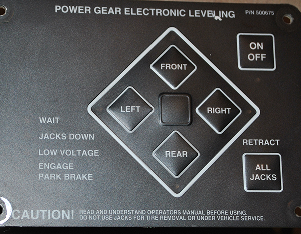
When I was having problems with the system before, I noticed that the previous owners of my coach had soldered the wires for the touchpad controller straight to the touchpad, (i.e. they had removed the square pin sockets on the wiring harness and the touchpad. I ordered a new touchpad from LCI. The new touchpad has a flat 4 pin connector as opposed to the square connector that the original had, so I ordered a wiring harness adapter for it also. Unfortunately, the wiring on the new harness adapter does not match the colors on my existing harness wires. On my existing harness, the wires are red, black, blue and white and on the harness adapter, the wires are red, black, green and yellow. I tried contacting LCI, but the info that they sent me was for a different touchpad model.
Does anyone have a similar touch pad that they can take a picture of the square connector and post it up for me so that I can wire up my touchpad? Or has anyone changed their touchpad for the newer one with the harness adapter and can tell me which wires match to which?
Thanks!
zog
__________________
2004 Damon Challenger 348W, 2011 Ford Taurus SEL
US Army veteran, USAF disabled veteran, (yes, I served in both branches).
|

|

|
 |
Join the #1 RV Forum Today - It's Totally Free!
iRV2.com RV Community - Are you about to start a new improvement on your RV or need some help with some maintenance? Do you need advice on what products to buy? Or maybe you can give others some advice? No matter where you fit in you'll find that iRV2 is a great community to join. Best of all it's totally FREE!
You are currently viewing our boards as a guest so you have limited access to our community. Please take the time to register and you will gain a lot of great new features including; the ability to participate in discussions, network with other RV owners, see fewer ads, upload photographs, create an RV blog, send private messages and so much, much more!
|
|
04-09-2016, 09:18 AM
|
#2
|
|
Senior Member
Damon Owners Club Workhorse Chassis Owner
Join Date: Jul 2015
Location: Montreal, Quebec
Posts: 162
|
SOLVED - Need help with wiring on Power Gear touchpad
OK, I found a guy in my campground who has the same touchpad. The wiring is as follows:
red - red
black - black
yellow - white
green - blue
__________________
2004 Damon Challenger 348W, 2011 Ford Taurus SEL
US Army veteran, USAF disabled veteran, (yes, I served in both branches).
|
|
|
|
|
09-28-2016, 09:53 AM
|
#3
|
|
Junior Member
Join Date: Aug 2016
Posts: 8
|
I too need help wiring this same Power Gear touch panel
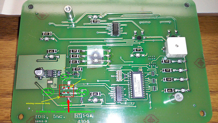
Recently bought a 05 Damon with this same 500675 touch panel leveling system. System was intermittent. Traced to loose plug on back of touch panel. Plug actually fell off while removing the panel. The four pins of rectangular connector are all that remain of the surface mounted connector. The plastic housing that holds the pins and ensures proper orientation of the cable connector is gone. As the connector is perfectly square, I have only a 25% chance of guessing the correct orientation. I definitely DO NOT want to blow this $500 dollar board through experimentation. No manufacturer docs are helpful.
Can anyone out there with this very same touch pad and the original square connector configuration (there are several newer variations) please help me get this back together right the first time. I have attached a couple pics of my situation. The cable connector has four wires: white, red, blue, and black. Also it has a alignment/locking tang that can be used to help me orient the connector as either Up, Right, Down, or Left.
Thanks. Living lopsided til then. Cliff
|
|
|
|
|
09-28-2016, 10:54 AM
|
#4
|
|
Senior Member
Damon Owners Club Workhorse Chassis Owner
Join Date: Jul 2015
Location: Montreal, Quebec
Posts: 162
|
Hi cliffgi,
If you check the attached picture, the red arrow points to where your ground, (black), wire connects.
I hope this helps.
zog
BTW, if you try soldering the wires directly to the panel, be very careful about how hot your soldering iron gets. I let mine get to hot and the pins came off and I couldn't get them back on! I had to spend $250.00 USD to replace the panel!
__________________
2004 Damon Challenger 348W, 2011 Ford Taurus SEL
US Army veteran, USAF disabled veteran, (yes, I served in both branches).
|
|
|
|
|
09-29-2016, 07:15 PM
|
#5
|
|
Junior Member
Join Date: Aug 2016
Posts: 8
|
Clarification of black wire pin.
Thanks Zog.
Just to be clear, please confirm that your red arrow is pointing to the lower-right pin.? If this be the case, the connector's locking tag will point to the right as circled in my original pic. This would put black on the lower-right pin, blue on the upper-right, red on the upper-left, and white on the lower-left. Is this correct?
thanks, Cliff
|
|
|
|
|
09-29-2016, 07:56 PM
|
#6
|
|
Junior Member
Join Date: Aug 2016
Posts: 8
|
Daaaa! I just realized that in my original pic of the circuit board, I mislabeled the left side of the connector as ""Right". Obviously, I meant left is left.
|
|
|
|
|
09-29-2016, 08:06 PM
|
#7
|
|
Junior Member
Join Date: Aug 2016
Posts: 8
|
Corrected image
Left is left and right is right.
|
|
|
|
|
09-29-2016, 08:28 PM
|
#8
|
|
Junior Member
Join Date: Aug 2016
Posts: 8
|
Ref soldering care.
Zog. Thanks for the soldering tip.
I had pretty much decided that soldering the board was a bad idea. The runs are very thin. I have decided that the best course is to cut the original harness connector from the harness to make a 6" pigtail. I'll install new connectors to the cut ends. Then I'll then carefully insert the original connector end of the pigtail over the pcb pins (properly aliened) and epoxy in place. After reinstalling the pcb's protective back-plate, I'll install a pigtail strain releaf attaching it to one of the back-plate mounting screws. Finally I'll attach the new pigtail to the wiring harness and secure the touch panel to my RV console.
That should do it.
When all is done, I'll attach a couple pics of the modification to this thread.
|
|
|
|
|
09-30-2016, 08:39 AM
|
#9
|
|
Junior Member
Join Date: Aug 2016
Posts: 8
|
Please Confirm Ground Pin
Zog. I just ran a continuity test between the circuit board pins to the TIPC6C595 IC chip on the board and discovered that the IC's GND pin, as shown on the chip's datasheet, has continuity to the upper-right circuit board pin, not the lower right as you indicated. Additionally, the upper right pin also has continuity to GND pins of other known chips on the board.
Are you absolutely sure that the the black pin is GND and that it matches up with the lower-right pin? What are you using as a reference?
Not trying to contradict you, but there is reason to question.
|
|
|
|
|
10-09-2016, 03:18 PM
|
#10
|
|
Junior Member
Join Date: Aug 2016
Posts: 8
|
Fixed my Power Gear Electronic Leveling - touch panel
To ALL.
Zog was right. For the original four pin plug on the 500675 touch panel, as viewed from the back of the touch panel (with IDS, Inc. text at bottom), the pin to wiring harness colors are as follows:
Lower-Right pin = black
Lower-Left pin = white
Upper-Left pin = red
Upper-Right pin = blue
Hope this helps someone.
|
|
|
|
|
|
Currently Active Users Viewing This Thread: 1 (0 members and 1 guests)
|
|
|
 Posting Rules
|
You may not post new threads
You may not post replies
You may not post attachments
You may not edit your posts
HTML code is Off
|
|
|
|
 » Recent Discussions
 |
|
|
|
|
|
|
|
|
|
|
|
|
|
|
|
|
|
|
|
|
|
|
|
|
|


 Linear Mode

