 |
|
 06-21-2014, 07:35 PM
|
#15
|
|
Senior Member
Join Date: Nov 2011
Posts: 124
|
Did some more searching and still confused. To shed a little light on this rv, it has an aftermarket 502 installed instead of the 454. The extra fuel pump was installed to correct some issues (don't know what). Previous owner died and I bought it from his estate. The fuel pump has its own toggle and the pump has been disconnect while doing this testing.
All 3 batteries (1 chassis and 2 coach) are dead. I have a new chassis battery and the draw is now .35amps not 5.
I used a tone meter to chase wires. I know 2 wires on the starter (large post) both pull the same .35 amps. I tested them individually and together (no change). The tone meter "sounds" while on the Aux Starter Solenoid (insert acronym here!). What is strange, the noise comes from both sides of solenoid. Here is a photo from what I can tell. Remember that my aux start switch actually starts/cranks the starter if the key is in the on position which I gather is incorrect. Currently I don't have any coach batteries connected for todays testing. 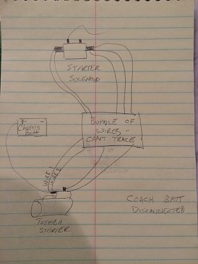
On the starter solenoid, left side has 2 wires and it can't separate them. Right side has 3 individual wires.
Labeled on photo, Wire 1 from starter, sounds the left post on solenoid and 2 if the 3 wires on the right. Wire 2 sounds the left and 1 wire on the right.
I also found 1 wire in engine compartment that has been cooked and I can see bare wire. I can chase it back to battery and it doesn't have anything to do with drain. I need to chase where it goes and replace but I don't think it's part of this issue. Photo of solenoid in question. 
Coach battery compartment. What's the amp looking device? My inverter is inside (I think). Also does it matter what position my inverter is in (off, to generator, to battery)??  .
Not sure of my next step. Install new coach batteries to continue testing? Use tone meter on Aux Start Switch to see why it cranks the starter and doesn't just give juice? I may try and remove this feature. I can always remove the coach battery and use jumpers if needed.
|

|

|
 |
Join the #1 RV Forum Today - It's Totally Free!
iRV2.com RV Community - Are you about to start a new improvement on your RV or need some help with some maintenance? Do you need advice on what products to buy? Or maybe you can give others some advice? No matter where you fit in you'll find that iRV2 is a great community to join. Best of all it's totally FREE!
You are currently viewing our boards as a guest so you have limited access to our community. Please take the time to register and you will gain a lot of great new features including; the ability to participate in discussions, network with other RV owners, see fewer ads, upload photographs, create an RV blog, send private messages and so much, much more!
|
|
06-21-2014, 07:38 PM
|
#16
|
|
Senior Member
Join Date: Feb 2010
Posts: 4,654
|
The thing with fins is your alternator isolator.
Center post goes to alternator and othrrs go to coach and chassis batteries.
__________________
Tony & Lori
1989 Country Coach Savannah SE
|
|
|
|
|
06-22-2014, 07:25 AM
|
#17
|
|
Senior Member
Join Date: Feb 2011
Location: Snowbird - Waterford Mi and Citrus Springs Fl.
Posts: 3,609
|
Next step - figure out what you want it to do, what you don't want it to do, and what it can do. Proceed as required?
The aux start thing, going by what you've said previously, if engaged with the engine running, is a recipe for disaster(or expensive repair bill). That would have to be disabled or rewired so it works properly on my coach ASAP.
That solenoid with all the wires going to it is fubar. It might be a nice start on what an aux start solenoid should look like? You have the ability to close it using the dash switch (aux. start), and you have what appears to be a couple of battery cables leading to the right side.
For it to work properly, each of the big side terminals should lead to a battery bank with heavy cable. Something of a size you could start the engine with (way bigger than what you have on the left in the pic). One side goes to the main, one side to the aux. This way, when you push the dash button the solenoid closes, connecting both battery banks together so you can give something everything available (usually the generator or starter).
So, that said, not sure what you have there now. The finned thing/amp/isolater might be dead, allowing power from the alternator to only the main or the aux. but not both. It works with diodes. There's one installed on each side between the center terminal and the outside terminal. If one of those diodes fail (not too unusual) just one side charges. If that happens, a trick to temp. fix/get you home is to put all 3 of the wires on the same terminal, effectively bypassing the isolator, connecting the alternator and both battery banks all together. Just like having that aux start button pushed down.
To test it, usually you would remove the 2 outside wires. With the engine running, those wires disconnected, you should have power on both the outside terminals. If one, or none, it's shot. Would advise not to get another like that one. It's more easily handled via a constant duty relay. Looks like a starter relay, but is designed to be held closed indefinitely. A starter relay will fry if you try that. They're commonly found on snow plow equipment.
Another way of doing the same thing as the temp patch above, would be to take the battery wires on the aux start solenoid and move those to one side. My guess is, that's what's happened here. The reason you have those 2 big heavy wires on the right side of the solenoid? Just a guess. I can't think of another reason that might be like that, but it doesn't explain what those wires on the left side are doing there...
Are we having fun yet?
-Al
__________________
1997 37' HR Endeavor, 275hp Cat, Freightliner
03 CR-V Blue Ox, Ready Brake
|
|
|
|
|
06-22-2014, 09:16 AM
|
#18
|
|
Senior Member
Join Date: Jun 2009
Posts: 1,528
|
You did not say what year your chassis is so I am using a 84 drawing to start with
For the stock 454 based P30, there should 2 fusible links attached to the main B+ cable post on the starter solenoid.
One fusible link goes to the Alternator B+ terminal and the Horn/Tail lights circuit in the under dash GM fuse panel. Horn/Tail lights section is separate from all other power in GM fuse panel. This allows the emergency flashers to work even if another power problem exists in another part of the system.
Please note that since you have a battery isolator installed (the amplifier looking thingy), it is inserted in the B+ fusible link path from the alternator B+.
The other one goes to a distribution block normally mounted under the front hood (feed for all other chassis circuits). It also goes to a starter relay (unique to P30 chassis). That starter relay is controlled by the neutral safety switch. The fusible link input is wrapped back to the "S" terminal of the starter solenoid (mounted to starter). When you place key to start and the neutral safety switch is in "P" or "N", the starter relay is energized allowing voltage to be applied to the solenoid "S" terminal.
The AUX Start switch and relay is NOT supposed to START the engine. It should ONLY cross connect the chassis and house batteries to allow the house battery to be used to assist the chassis battery to start the engine when the chassis battery has been drained. It should be connected such that you depress the AUX Start switch (cross connects batteries) then place the ignition key to START. Think in terms of a built in set of jumper cables. The second wire to the "S" terminal is the one someone improperly wired from the AUX START switch.
GM started electric fuel pump installation in mid year 1985. Early 85 chassis' do not have it unless it was added by a GM dealer, RV Mfg, or as aftermarket. Either way, as shown in the Chevrolet MOtorhome Service Guide, it should be ran through the oil pressure swtich (emergency shutoff for safety) and a fuel pump relay (mounted to side wall in engine compartment).
You need to know which of the 2 fusible link wires attached to the B+ solenoid post (battery cable) is causing the draw. Is it the one for the alternator/tail lights or the main power feed that runs to the main terminal block under the front hood?
Dave
|
|
|
|
|
06-22-2014, 08:42 PM
|
#19
|
|
Senior Member
Join Date: Nov 2011
Posts: 124
|
Dave78Chief, Its an 86 Holiday Rambler Imperial on the P37 chassis. I found this online from another one of your posts.

I assume that my battery solenoid is here...

and not here

If that is true, where does the Aux Start Solenoid (last pic) come into play in your schematic?
|
|
|
|
|
06-23-2014, 05:55 AM
|
#20
|
|
Senior Member
Join Date: Feb 2011
Location: Snowbird - Waterford Mi and Citrus Springs Fl.
Posts: 3,609
|
Wowee. 2 relays AND a diode type isolator. I can see where that might create some confusion.
Aux start sol will (should?) have HEAVY cables leading to and from it as it will have engine starting loads run through it. It would be installed in the circuit similar to the sol shown in that schematic.
Sol. shown in schematic COULD function as either an isolator or aux start relay IF the chassis charging/electrical system hadn't been tampered with already by the coach manf. Just remember that a solenoid functioning as an isolator HAS to be rated for constant duty. Starter solenoids are not....
The relay in your last pic, judging by it's proximity to the alternator and the size wires attached to it, is more likely intended as an isolator. The trouble here is that you already have shown us a pic of the diode type isolator? Are they both still in the circuit, or is it possible one has had the wires to it cut?
The relay in the second pic looks like it's been bypassed as the heavy cables are both on one side of it?
I would be tracing some of this wiring personally. Shouldn't take that long to get an idea of where each is headed, then you can confirm as required.
__________________
1997 37' HR Endeavor, 275hp Cat, Freightliner
03 CR-V Blue Ox, Ready Brake
|
|
|
|
|
06-23-2014, 06:08 AM
|
#21
|
|
Senior Member
Join Date: Jun 2009
Posts: 1,528
|
I have to take my wife to the doctor for some tests this AM. Will see if I can put something together later today to help you with this.
Dave
|
|
|
|
|
06-23-2014, 08:49 PM
|
#22
|
|
Senior Member
Join Date: Jun 2009
Posts: 1,528
|
Trying to establish why there are 2 solenoids.
Do you have a Battery Disconnect Switch and a Aux Battery switch?
Regarding this solenoid at the battery:
Does the B+ from the chassis battery go to one side and the B+ from the House battery go to the other side.
Dave
|
|
|
|
|
06-24-2014, 08:25 PM
|
#23
|
|
Senior Member
Join Date: Jun 2009
Posts: 1,528
|
The solenoid on the top by the air cleaner is the Magnetic Start Relay (GM P/N 1115616 [old GM P/N 1114535]). Ensures you get solid B+ voltage to the "S" terminal on the starter solenoid (mounted on starter) when you place ignition key to start. There should be wires on both small terminals. One of yours does not look like it has a wire connected to it. With the modifications the PO made, you are going to have to get the chassis wiring diagrams to make sense of this. The 86 & 87 wiring diagrams are difficult to follow with the way GM did them. Here is a 88 version http://johnnynightstick.s3.amazonaws...lete_11x17.pdf
Go to pdf page 351 (book page E-17) for the P30 Starter circuit
The one down by the battery is the AUX Start relay used to cross connect the chassis and house battery systems. That is the one I show in this drawing:

The GM books cover both pickups and P30 chassis. A pickup does not use a magnetic starter relay which is why it is not reflected in that drawing I modified. The magnetic starter relay is inserted in the top line that goes back to the "S" terminal on the starter solenoid from the ignition switch.
Dave
|
|
|
|
|
06-25-2014, 06:44 AM
|
#24
|
|
Senior Member
Join Date: Feb 2011
Location: Snowbird - Waterford Mi and Citrus Springs Fl.
Posts: 3,609
|
Dave, not questioning you right or wrong, just looking for your thoughts regarding the value/objective of this mess for the purpose of "Ensures you get solid B+ voltage to the "S" terminal". That looks like a lot of complexity for that objective? The "S" terminal being referred to here is the one that closes/energizes the starter solenoid on the starter, right?
Guessing, just by looking at it the pic, that purple wire (#2) is probably coming from the ign. switch "start" position. Originally/normally, it went/goes to the "S" terminal on the starter solenoid. With this set up, it looks like it's now being used to close this relay with the ign switch in "start" position, taking power from wherever those wires on the right are coming from (the starter "B" terminal?), and sending it out to the wire on the left - which goes to where the purple wire usually goes - the "S" terminal.
If that's the case, this apparatus might be removed on my coach, and the purple wire restored to it's normal home on the "s" terminal - in the name of simplicity. I can't imagine there would be that significant of a voltage/amperage loss to make this thing necessary. We're just supplying power to close a solenoid, right? Judging by the gauge of that purple wire, it should have plenty of capacity on it's own?
My thought anyway...
As the starter isn't on the non functional list, I think this mess might be an issue I revisit once the rest of the coach is functioning.... -Al
Oh, BTW, the black wire with the yellow tracer in that same pic? It looks like it might be getting full time power. Betting it's not supposed to be. Could be the source of the draw you're hunting. 30 year old memory says it might be the wire that used to supply straight 12v to the ign. coil while starting. Should be on that empty terminal on that relay. Here, it might lead to the fuel pump relay, closing it with the key in the start position? Just guessing....
__________________
1997 37' HR Endeavor, 275hp Cat, Freightliner
03 CR-V Blue Ox, Ready Brake
|
|
|
|
|
06-25-2014, 09:24 PM
|
#25
|
|
Senior Member
Join Date: Jun 2009
Posts: 1,528
|
Quote:
|
If that's the case, this apparatus might be removed on my coach
|
The magnetic Start relay is a Motorhome chassis only addition. Was not used on pickup trucks. I can only guess as to why GM felt it necessary to add it (hard start issues due to heat on a MH 454?) You have to remember GM did not control what items the MH Mfg added to the base design so increased loads could draw the voltage down such that it created problems. That extra relay ensures sufficient voltage is applied to the "S" terminal in START.
Quote:
|
Oh, BTW, the black wire with the yellow tracer in that same pic?
|
I am not sure which one you are referring to.
Dave
|
|
|
|
|
06-26-2014, 05:17 AM
|
#26
|
|
Senior Member
Join Date: Feb 2011
Location: Snowbird - Waterford Mi and Citrus Springs Fl.
Posts: 3,609
|
This apparatus might make sense if the ignition switch were at the opposite end of the coach. First, for our purposes here, I don't see the need for enhanced voltage/amperage for a wire whose only purpose is to close/engage the starter solenoid. Second, I don't know where they would get enough extra power (as compared to a pick-up's wiring) to justify trying to "boost" power to the solonoid.
Familiar with the high drag, hot starter scenario, but that applies to the starter motor itself. Never heard of issues trying to close/engage the solenoid where this apparatus might prove itself useful.
Pic with blk/yel wire I was talking about is 4th in post #15. Looks like it might have a fusible link on it. As mentioned, just a guess/old memory. My only point is I'd check it.
-Al
__________________
1997 37' HR Endeavor, 275hp Cat, Freightliner
03 CR-V Blue Ox, Ready Brake
|
|
|
|
|
06-26-2014, 05:50 AM
|
#27
|
|
Senior Member
Join Date: Nov 2011
Posts: 124
|
I printed out the electrical schematic. Thanks Dave for the info
I'm hoping this weekend I will have some time to dig in and find out exactly where all the wires come and go on both of the solenoids.
Hopefully it will be obvious once it's mapped out.
|
|
|
|
|
06-26-2014, 07:30 PM
|
#28
|
|
Senior Member
Join Date: Jun 2009
Posts: 1,528
|
I see what you mean now. Very well could be however, the much bigger problem is there is no connection to the small post on the relay which means it never is energized.
Dave
|
|
|
|
|
|
|
Currently Active Users Viewing This Thread: 2 (0 members and 2 guests)
|
|
|
 Posting Rules
|
You may not post new threads
You may not post replies
You may not post attachments
You may not edit your posts
HTML code is Off
|
|
|
|
 » Recent Discussions
 |
|
|
|
|
|
|
|
|
|
|
|
|
|
|
|
|
|
|
|
|
|
|
|
|
|


 Linear Mode

