Hi,
I've posted a few questions here and there as I prepared for my install of solar on my 2017 DSDP 4310. I appreciate the information several members provided as it gave me enough info to get started and complete the installation.
After surveying the roof, I really felt there was no reason to put new holes in the roof. Instead, I decided to mount the panels to a rack constructed from
80/20 T-slotted profiles mounted to the brackets that hold the side valences to the roof of the coach. Not all of the brackets are aligned front to back on the left and right side so I had to run one of the profile rails fore and aft on the driver's side to meet up with a cross bar coming from the passenger side. With these rails, I was able to mount the panels about 1.5 inches below the height of the front air dam and the side rails. I believe that will limit the force the panels experience going down the road.

This round of installations will be for a total of three 450 watt panels. Two mounted all the forward as seen in the picture above and one mounted on the driver's side opposite the skylight and vent fan for the mid bath (on the passenger side).
As I mentioned, my coach apparently wasn't ordered with the pre-wire option, so I had to figure out running the wiring myself. My coach did have both an old cellular booster and the Winegard 4G/WiFi bridge unit. I'm not using either of those and they both had wires running into a plate on the backside of the front air dam. I pulled those units off and got rid of their cables. I was able to run 3 x 10/2 cables down through the hole and cover them with the existing plate. I had to modify the plate slightly by cutting out the plastic ribs designed to separate four different cables. The 3 wire bundles came into the cavity above the windshield. To access this, I pulled down the shade mechanism and the trim piece it mounts on. With that down, I was able to find the wires (using a fiberglass wire fishing pole).

I then ran the wire down the driver's side pillar at the corner of the windshield:

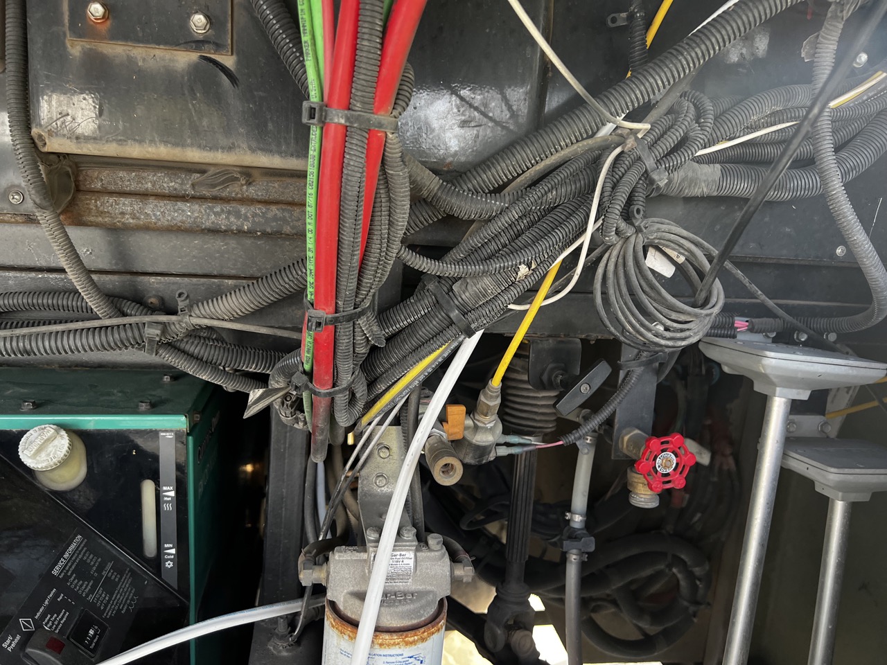
I then ran a rod through the foam at the base of the pillar and forced the wire through the hole I'd created. It came out in the corner of the generator compartment:

I then ran the wires through the generator compartment, to the front of the driver's side frame rail and back to the battery compartment:
Once there, I added a small hole from the generator compartment to the first storage bay so I could run all the wires through to this compartment where I would mount the MPPT controllers.
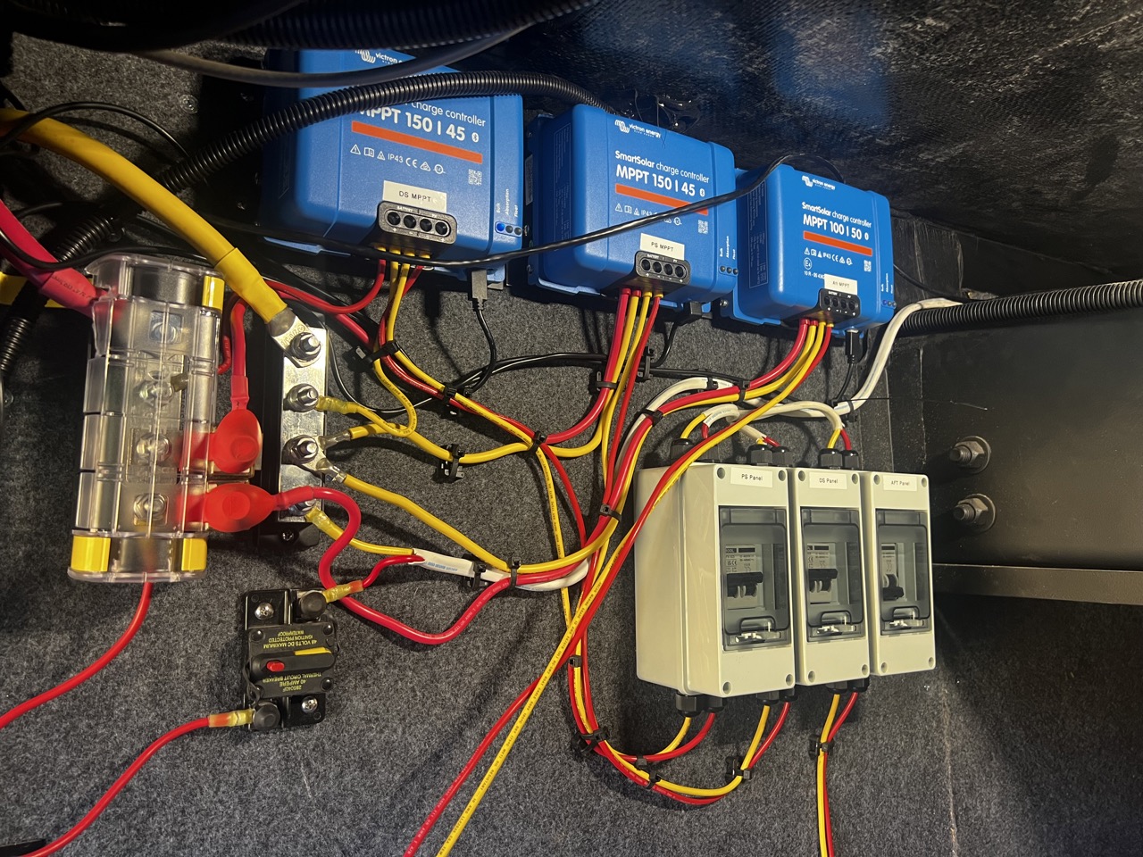
Previously, I've added 600 amp bus bars for positive and negative distribution in the battery compartment. I've also converted to LiFePO4 batteries. I ran 4/0 cable from the battery compartment to bus bars in the first bay so I could add bus bars there to connect each MPPT controller. I connected the 10/2 cables coming down from the panels through a disconnect switch and into the MPPT charge controllers. Here's what it looks like all wired up:
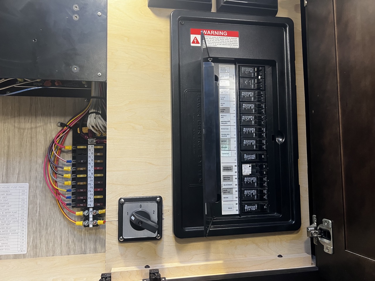
With that done, I wanted the ability to run my middle AC unit from batteries and solar, rather than just from the shore power or the generator. I added a rotary switch so I can select between the inverter bus and the pre-inverter bus on the main AC panel. I mounted the switch just to the left of the panel.
Later this week, we will hit the road with this setup for the first time and I'll be better able to see how it all works. In the meantime, any questions?
-Ben


 Linear Mode


