 |
|
 08-01-2019, 04:42 PM
|
#169
|
|
Member
Join Date: Aug 2018
Posts: 67
|
Quote:
Originally Posted by lonfu

Looks like some one pulled the pinion gear out of the gear box, bad news, going to have to replace the gear box... easy $100, then the motor, $50 to $100 depending on source... might as well buy a new unit because there is no way to test the controller. Getting up there price wise for replacement stuff...
|
Not sure why you say there is no way to test the controller. Here is the manual that shows the step controller testing procedures I bought a gear box for $61 and a motor for $72. With tax the total came to ~$142. So all in on the step I have $317 so far. I don't think that is too bad for a platinum series step. The gear box and motor should be here tomorrow and I will know by Saturday if I have a fully functional step.
|

|

|
 |
Join the #1 RV Forum Today - It's Totally Free!
iRV2.com RV Community - Are you about to start a new improvement on your RV or need some help with some maintenance? Do you need advice on what products to buy? Or maybe you can give others some advice? No matter where you fit in you'll find that iRV2 is a great community to join. Best of all it's totally FREE!
You are currently viewing our boards as a guest so you have limited access to our community. Please take the time to register and you will gain a lot of great new features including; the ability to participate in discussions, network with other RV owners, see fewer ads, upload photographs, create an RV blog, send private messages and so much, much more!
|
|
08-02-2019, 08:43 AM
|
#170
|
|
Senior Member
Newmar Owners Club Winnebago Owners Club Freightliner Owners Club
Join Date: Mar 2016
Location: Kingman Az
Posts: 1,686
|
Quote:
Originally Posted by dbemowsk
Not sure why you say there is no way to test the controller. Here is the manual that shows the step controller testing procedures I bought a gear box for $61 and a motor for $72. With tax the total came to ~$142. So all in on the step I have $317 so far. I don't think that is too bad for a platinum series step. The gear box and motor should be here tomorrow and I will know by Saturday if I have a fully functional step. |
great price on the gear box and motor, be sure to leave your sources here for other folks. The instructions "link" is for testing the data input leads that go to the controller box. Ground, power, door switch and such, all good things to know. But there is no "control box tester" like is available for frig and furnace controllers, that I know of. If all the data input leads are working correctly then it assumes that the box is bado...
At $500 for one of these steps these days sounds like you are less than the price by at least $200 then.. very cool...
__________________
May your black water hose never break!
|
|
|
|
|
08-02-2019, 09:35 PM
|
#171
|
|
Member
Join Date: Aug 2018
Posts: 67
|
Quote:
Originally Posted by lonfu
great price on the gear box and motor, be sure to leave your sources here for other folks. The instructions "link" is for testing the data input leads that go to the controller box. Ground, power, door switch and such, all good things to know. But there is no "control box tester" like is available for frig and furnace controllers, that I know of. If all the data input leads are working correctly then it assumes that the box is bado...
At $500 for one of these steps these days sounds like you are less than the price by at least $200 then.. very cool...
|
I ordered both parts from Amazon. I received them both today. The problem with the gear box that I ordered was that it must have been an open box returned item. The gear that I needed was missing. I bet someone that needed that gear like I did, ordered a gear box, took the gear and returned the rest of the gear box. I called Amazon and for the hassle, they sold me one that was listed on the site as brand new for $73 and gave me an extra $25 off. Plus they sent me a return shipping label. So after all that, $73 plus tax minus the $25, I got the gear box for $51.26. With my Prime 1 day shipping, I will have it tomorrow.
|
|
|
|
|
08-03-2019, 11:38 PM
|
#172
|
|
Member
Join Date: Aug 2018
Posts: 67
|
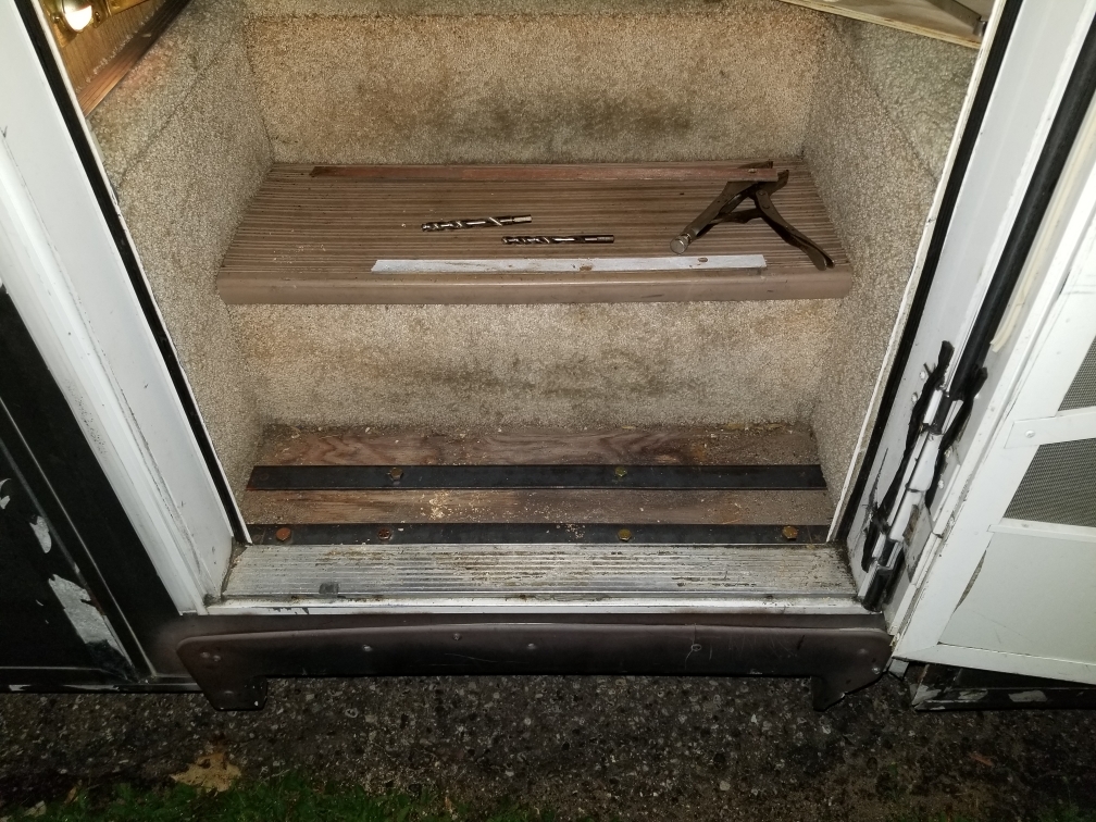
So I am preparing things for mounting my new electric step. I got a couple sticks of flat plate steel for strength. I marked the holes for mounting the step on the steel bars. I didn't think that there was as much wood as there was under that first step. I drilled it and had to use 4 inch bolts. For added strength I went with schedule 8 bolts. This pic shows the steel bars in place. I think I have plenty of reinforcement for the step.
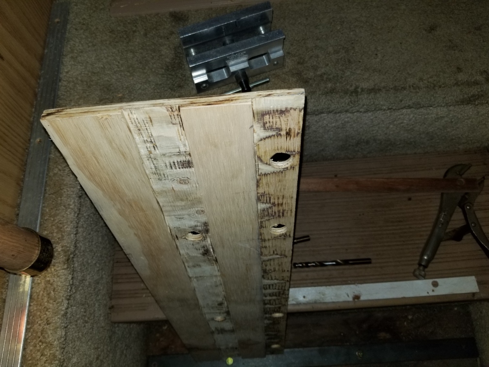
I pulled the step apart and found that the step had a piece of 3/8" plywood that was shimmed up closer to the door. I decided to remove that and replace it with a piece of 1/2". The 1/2" was thick enough to cut channels to fit over the steel bars and drill holes for the heads of the bolts.
This is the board in place over the steel bars and bolts. I will be screwing this plywood down with some #8 screws. The heads of the bolts are nearly perfectly flush with the top of the plywood.
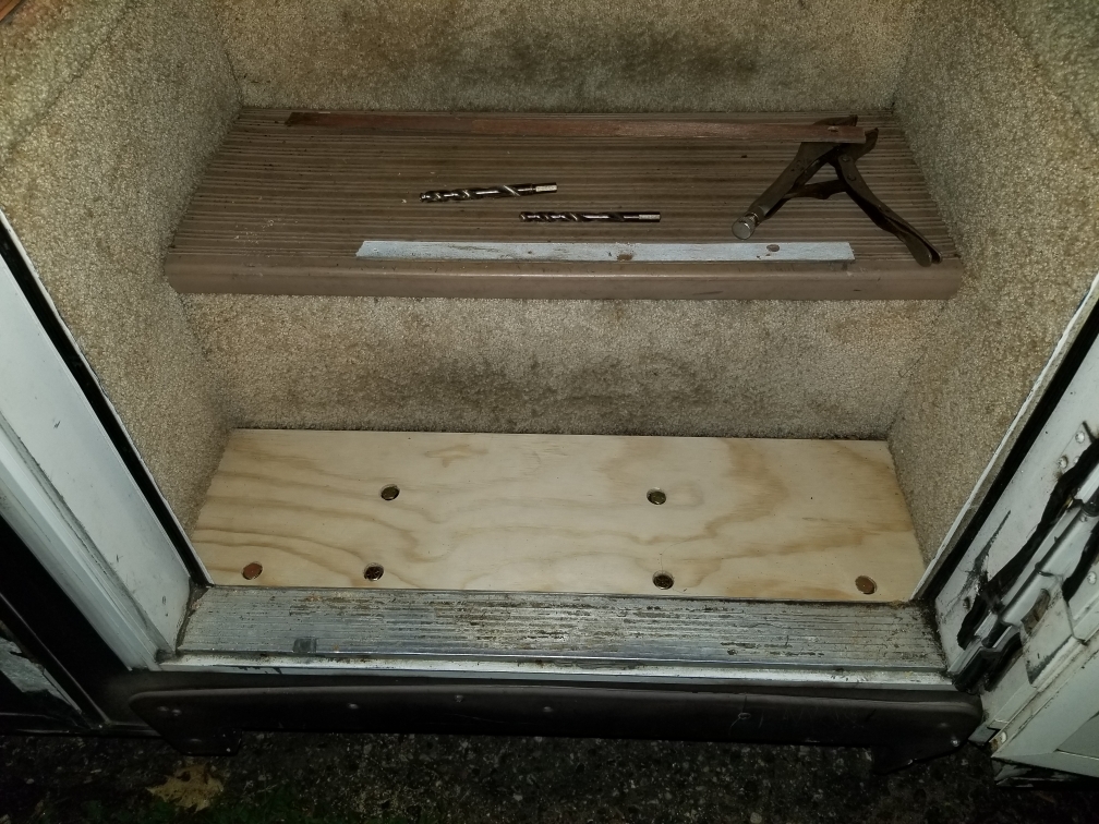
Tomorrow I will be lifting the step into place and getting the front 6 bolts seen in the pics secured. I don't have a picture of it, but the back side of the step is going to hang over the step edge a bit according to my cardboard template, so my plan for that is to take this piece of angle iron and use it as an L bracket that will bolt the back side of the electric step to the toe board side of the step inside the RV.

|
|
|
|
|
08-04-2019, 05:24 PM
|
#173
|
|
Member
Join Date: Aug 2018
Posts: 67
|
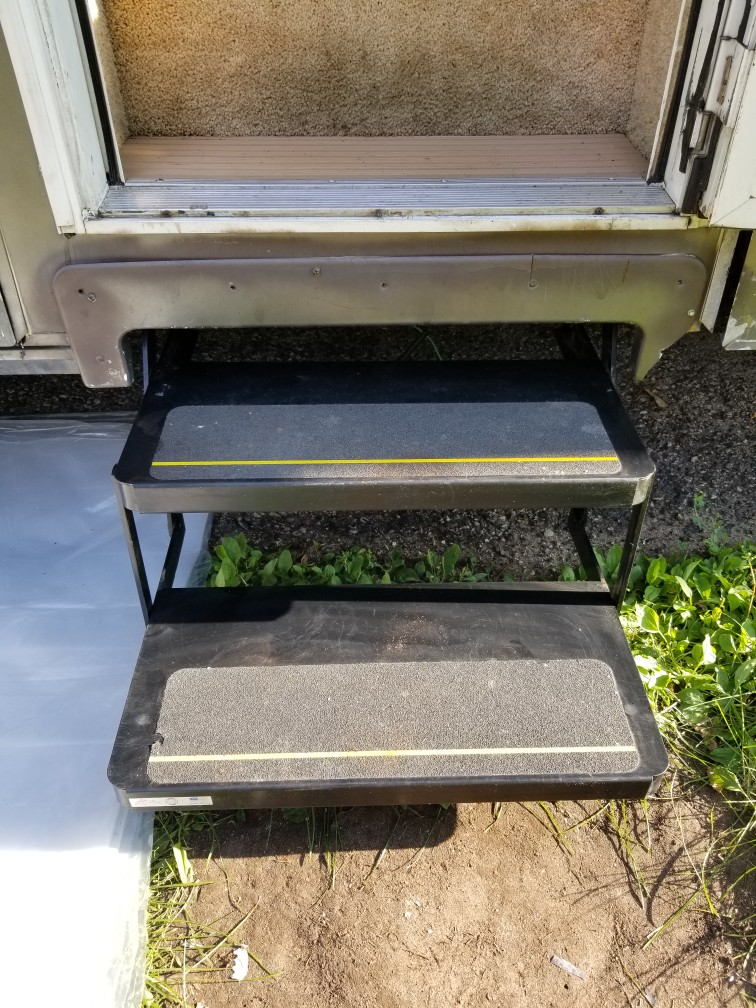
So I now have the new step fully mounted to the chassis.
The next step is to get it operating. This is a picture of the original step connector from my 98 Pace Arrow.

This is the new step connector.
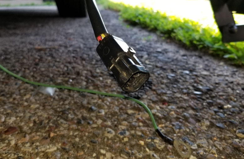
The new step that I installed is a Kwikee step with an IMGL controller. The original step I am sure had to have been a pre IMGL being that the coach is a 98. The steps with the IMGL controllers didn't come out till around 2005. My issue here is that I have to figure out the original connector wiring so I can wire a new connector to it. I have already ordered the connector and some heat shrink waterproof butt connectors to do the splicing. The color coding is different though and I don't know what the original wiring is to match it up. There are two white, one brown and one blue wire. One of the white wires is a heavier gauge wire which I assume is the main power wire. When I test that one, I have 13.6 volts (coach is plugged in to AC power). I need to know what the smaller white, brown and blue wires are for. Does anyone know where I can get that information?
|
|
|
|
|
08-04-2019, 08:15 PM
|
#174
|
|
Senior Member
Fleetwood Owners Club
Join Date: May 2013
Posts: 1,485
|
This might (or might not) help
According to my Kwikee Step owner's manual the wiring on the coach side is as follows:
yellow - goes to IGN at fuse box (may have 5A inline fuse - retracts step when IGN is ON - safety feature)
red - goes to battery disconnect switch (may have 25A inline fuse; might be white - main power lead - this is your heavier wire)
white - goes to the power switch on the wall
brown - goes to chassis ground through the door switch (the door jamb contacts, not the on/off switch)
Your wires obviously don't match this (surprise, surprise). The following is an educated guess (take it with as many grains of salt as you want):
Your white 13.6 volt wire appears to be your main power. That would correspond to the red wire on your step. Either your smaller white or blue wire should have voltage when the ignition is on (to automatically retract the step) but not when it is off. That should correspond with the yellow wire on the step. The brown wire is probably your ground. You might be able to trace it to the chassis to verify. It would correspond with the brown wire on the step. That leaves one wire (either blue or white, whichever one wasn't hot with the ignition on). I'm guessing that wire would have power from the wall on/off switch, easy to test for voltage. That would correspond with the white wire on the step. Your step controller should have 2 loose green wires(might only have 1) . Those (or it) ground(s) to the chassis. Again, this is only an educated guess based on reading the Kwikee schematic. Don't threaten me with a horrible fate or insult my ancestors if some of this turns out to be incorrect...
__________________
Dave RVM#66 and Carol
1998 Pace Arrow Vision
Seeing the USA - 200 miles at a time
|
|
|
|
|
08-04-2019, 11:46 PM
|
#175
|
|
Member
Join Date: Aug 2018
Posts: 67
|
Quote:
Originally Posted by daveandcarol
According to my Kwikee Step owner's manual the wiring on the coach side is as follows:
yellow - goes to IGN at fuse box (may have 5A inline fuse - retracts step when IGN is ON - safety feature)
red - goes to battery disconnect switch (may have 25A inline fuse; might be white - main power lead - this is your heavier wire)
white - goes to the power switch on the wall
brown - goes to chassis ground through the door switch (the door jamb contacts, not the on/off switch)
Your wires obviously don't match this (surprise, surprise). The following is an educated guess (take it with as many grains of salt as you want):
Your white 13.6 volt wire appears to be your main power. That would correspond to the red wire on your step. Either your smaller white or blue wire should have voltage when the ignition is on (to automatically retract the step) but not when it is off. That should correspond with the yellow wire on the step. The brown wire is probably your ground. You might be able to trace it to the chassis to verify. It would correspond with the brown wire on the step. That leaves one wire (either blue or white, whichever one wasn't hot with the ignition on). I'm guessing that wire would have power from the wall on/off switch, easy to test for voltage. That would correspond with the white wire on the step. Your step controller should have 2 loose green wires(might only have 1) . Those (or it) ground(s) to the chassis. Again, this is only an educated guess based on reading the Kwikee schematic. Don't threaten me with a horrible fate or insult my ancestors if some of this turns out to be incorrect...
|
I appreciate your thoughts. I had similar thoughts, so no insults will be thrown your way. I have the Kwikee IMGL step controller testing procedure pages printed out that tell me what the wires on the step do and how to test those. The brown wire on the step is from the magnetic door switch to operate the step when the door is opened or closed. My concern was that some wires get power (i.e. ignition on power) and I didn't want to accidentally connect the brown wire for the controller to one of the power leads and potentially burn out the controller on the step. I guess it will be a process of testing and elimination. I did some more testing since I posted that and found that the smaller white wire is the ignition power wire. I have not figured out anything with the blue or brown wires as of yet. I tried the magnetic door switch and testing continuity to ground between both of those wires and I am not getting anything. I didn't test with the step switch on on the panel inside the door yet, so I think I will test that tomorrow. The new connector is due to arrive on Tuesday, so I would like to have this all figured out so all I have to do is wire on the connector and plug it in. It's all in knowing how the step is supposed to operate. With the switch on the panel inside the door, what is it's function/purpose? Will that completely power on or off the step to where it won't operate without that switch on? Will I see magnetic door switch activity at the step connector with that switch in the off position, or only when it is on?
|
|
|
|
|
08-05-2019, 08:43 AM
|
#176
|
|
Senior Member
Newmar Owners Club Winnebago Owners Club Freightliner Owners Club
Join Date: Mar 2016
Location: Kingman Az
Posts: 1,686
|
Looks like a good job of mounting. The 4 bolts in the front are the key.
consider running a switch wire next to your bed, that way when you are boondocking and you hear someone walking around your coach you can run the step and scare the "steps" out of them... I don't recomend mounting a mini-gun on the bottom side.... it will drag... 
just joking, but I put an switch to shut off the power to the entire step for 2 reasons, one is that way I can shut the stupid light off, saves the batt, 2nd when I park near a high curb, I can lock the step in so it doesn't get damaged on the curb... this has saved my step quit a few times... 
__________________
May your black water hose never break!
|
|
|
|
|
08-05-2019, 01:28 PM
|
#177
|
|
Senior Member
Fleetwood Owners Club
Join Date: May 2013
Posts: 1,485
|
The on/off switch inside the coach lets you turn off the power when the steps are out (when you are parked for a while) so they don't cycle every time you open or close the door. Conversely, the IGN wire draws the steps in automatically when you start the engine in case you forget to turn the other switch back on (so you don't drive away with them hanging out)...they will still extend if you open the door (there's probably a small warning sticker near the switch cautioning you to make sure they are extended before stepping outside).
__________________
Dave RVM#66 and Carol
1998 Pace Arrow Vision
Seeing the USA - 200 miles at a time
|
|
|
|
|
08-05-2019, 05:03 PM
|
#178
|
|
Member
Join Date: Aug 2018
Posts: 67
|
Quote:
Originally Posted by daveandcarol
The on/off switch inside the coach lets you turn off the power when the steps are out (when you are parked for a while) so they don't cycle every time you open or close the door. Conversely, the IGN wire draws the steps in automatically when you start the engine in case you forget to turn the other switch back on (so you don't drive away with them hanging out)...they will still extend if you open the door (there's probably a small warning sticker near the switch cautioning you to make sure they are extended before stepping outside).
|
So with the switch in the on (up) position, the step should open and close with the door, but with it in the off (down) position it locks the step in the extended position. If the switch is in the off position when the step is retracted (folded in), does that lock the step from extending if the door is opened? I did see the warning sticker you mentioned, I am assuming that is why that is there.
|
|
|
|
|
08-05-2019, 05:16 PM
|
#179
|
|
Member
Join Date: Aug 2018
Posts: 67
|
Quote:
Originally Posted by lonfu
Looks like a good job of mounting. The 4 bolts in the front are the key.
|
Thanks. I tried to error on the side of safety. I was surprised to see that there was 3 inches of wood that I had to go through to bolt it on. For the 4 bolts on the front, driling through was solid wood from top to bottom. For the two behind that, I felt a small air gap when drilling, but it didn't seem to be much.
Quote:
Originally Posted by lonfu
consider running a switch wire next to your bed, that way when you are boondocking and you hear someone walking around your coach you can run the step and scare the "steps" out of them... I don't recomend mounting a mini-gun on the bottom side.... it will drag... |
That almost seems useful in an evil kind of way... LOL...
Quote:
Originally Posted by lonfu
just joking, but I put an switch to shut off the power to the entire step for 2 reasons, one is that way I can shut the stupid light off, saves the batt, 2nd when I park near a high curb, I can lock the step in so it doesn't get damaged on the curb... this has saved my step quit a few times... |
I guess that was one of the things I was questioning about the step switch on the panel just inside the door. I was wondering if that would stop the step from extending if I have that in the off position. Also, I thought that the light was only on when the step was extended. It was my understanding too, at least with the IMGL step controllers that if the step hit an obstacle while extending that the step would stop and possibly retract back in. I could be wrong on that.
|
|
|
|
|
08-05-2019, 07:27 PM
|
#180
|
|
Senior Member
Fleetwood Owners Club
Join Date: May 2013
Posts: 1,485
|
I don't believe turning off the switch 'locks' the step in the extended position. As I understand it, the motor works like a modern power window does. When it hits the stop (or a curb or similar) the motor shuts off automatically. The mechanical reduction of the gear assembly holds the step in place. All the switch does is deactivate the door contact switch so it doesn't get the 'retract step' signal when you close the door. The IGN lead apparently acts as a safety override to retract the step when you turn on the engine so you won't travel with it extended.
At least I think this is how it is all supposed to work. My career was in architecture, not engineering...
__________________
Dave RVM#66 and Carol
1998 Pace Arrow Vision
Seeing the USA - 200 miles at a time
|
|
|
|
|
08-06-2019, 08:06 PM
|
#181
|
|
Member
Join Date: Aug 2018
Posts: 67
|
Quote:
Originally Posted by daveandcarol
I don't believe turning off the switch 'locks' the step in the extended position. As I understand it, the motor works like a modern power window does. When it hits the stop (or a curb or similar) the motor shuts off automatically. The mechanical reduction of the gear assembly holds the step in place. All the switch does is deactivate the door contact switch so it doesn't get the 'retract step' signal when you close the door. The IGN lead apparently acts as a safety override to retract the step when you turn on the engine so you won't travel with it extended.
At least I think this is how it is all supposed to work. My career was in architecture, not engineering...
|
Well, from my testing on the wires, the switch does not affect the door switch at all. The door switch simply makes or breaks a connection to ground. When I first tested the wire that I figured was for the door switch, it didn't appear to do anything. As I was working on things underneath, I saw two wires that were hanging not connected to anything. Right near them was two blue ring connectors that were attached to the frame of the vehicle with no wires attached. Logic said that those two wires were ground wires for something. In testing the two, I found that one of them was the ground for the door switch. I now have both of those wires grounded.
Good news, the step functions. The guy that I bought the step from had mentioned that the platinum series steps used a door switch that is reversed from the normal door switches used in the coaches. I found out that he is correct. My door switch is a magnetic reed switch that is normally closed. When you close the door and the magnet is by it, it breaks the ground connection. So the step retracts when I open the door and extends when I close the door. I am in the process of making a new one from parts I dug out of my electronics parts bins.
For anyone that stumbles across this looking for older step wiring, here is what I found:
White - 12ga - Main power supply
White - 16ga - Ignition override power (12 volts when key is in the on position)
Blue - 16ga - Step lockout switch (12 volts when the switch is on)
Brown - 16ga - Door switch (mine is a magnetic switch that contacts ground when the door is open and open when the door is closed)
So to the new step connector, this should be the color order:
Original - New connector
White 12ga - Red
White 16ga - Yellow
Blue 16ga - White
Brown 16ga - Brown
ALWAYS verify your wiring prior to installing the new connector as your wiring may be different. This information should be a starting point for you though.
|
|
|
|
|
08-06-2019, 08:25 PM
|
#182
|
|
Senior Member
Fleetwood Owners Club
Join Date: May 2013
Posts: 1,485
|
The door switch (when you get it working correctly) should extend the steps even with the engine running. The control box apparently overrides the IGN retract signal. The warning sticker may be there for "attorney repellent" as much as anything...Like I said, most of this is from observing the functions and interpolating from the schematics. My own opinion of electronics is that it is about 10% electricity and 90% black magic...I grew up watching mechanical things work, I can't watch the electrons work...
__________________
Dave RVM#66 and Carol
1998 Pace Arrow Vision
Seeing the USA - 200 miles at a time
|
|
|
|
|
|
|
Currently Active Users Viewing This Thread: 1 (0 members and 1 guests)
|
|
|
| Thread Tools |
Search this Thread |
|
|
|
| Display Modes |
 Linear Mode Linear Mode
|
 Posting Rules
|
You may not post new threads
You may not post replies
You may not post attachments
You may not edit your posts
HTML code is Off
|
|
|
|
 » Recent Discussions
 |
|
|
|
|
|
|
|
|
|
|
|
|
|
|
|
|
|
|
|
|
|
|
|
|
|


