 |
|
 04-28-2007, 12:34 AM
|
#1
|
|
Senior Member
Join Date: Apr 2007
Location: Hurricane, Utah
Posts: 177
|
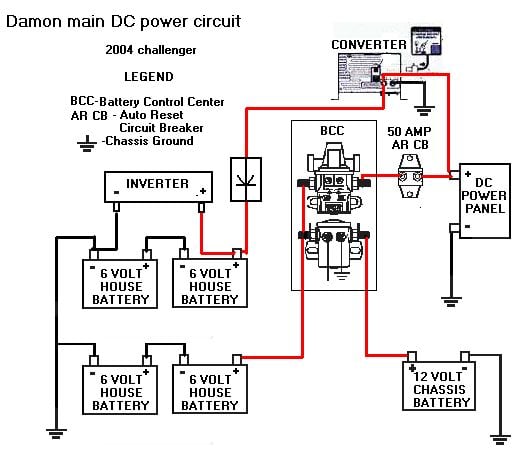
Here is a wiring diagram I made of my 2004 challenger main DC wiring(with a few cosmetic errors). The second drawing is from the Intellitec battery control center service manual, that I posted earlier. BCC PDF This has a lot of good info and I encourage any one who has this, to print it out.
The big fault in this wiring scheme is the absurd distance Damon ran the charge line from the converter to the battery. On the drawing, it looks pretty short but in actual fact it is about 65 feet. This creates a huge voltage drop and increases generator run time when boondocking due to less amps being pumped into the battery. I will post my fix and another drawing later.


Sam
__________________
2004 315 Damon Challenger
Ford F53 20,500
|

|

|
 |
Join the #1 RV Forum Today - It's Totally Free!
iRV2.com RV Community - Are you about to start a new improvement on your RV or need some help with some maintenance? Do you need advice on what products to buy? Or maybe you can give others some advice? No matter where you fit in you'll find that iRV2 is a great community to join. Best of all it's totally FREE!
You are currently viewing our boards as a guest so you have limited access to our community. Please take the time to register and you will gain a lot of great new features including; the ability to participate in discussions, network with other RV owners, see fewer ads, upload photographs, create an RV blog, send private messages and so much, much more!
|
|
04-28-2007, 10:40 AM
|
#2
|
|
Junior Member
Join Date: Jun 2005
Posts: 1
|
Test
|
|
|
|
|
04-28-2007, 12:38 PM
|
#3
|
|
Senior Member
Join Date: Apr 2007
Location: Hurricane, Utah
Posts: 177
|
Here is the modification I made. I added the wire in blue and disconnected the existing wire to the converter and taped it off. I used a # 2 wire for this which is overkill, a #4 would have done the job since it is only 22 feet. The idea here is to keep the max charger output(60 amps in my case) to under a 3% voltage drop. This brought my max charge rate from 33 amps to 56 amps. Of course the 56 amps tapers off as the battery becomes charged, but this gives you an idea how much of an improvement it was. The one disadvantage of this mod is you cannot disconnect the converter from the batteries, which with the PD converter and charge wizard, you never want to do anyway.
There is nothing unsafe or wrong with the way Damon does it, but if you boondock and want to keep gen runtime to a minimum this is a good mod. With gas at 3 bucks a gallon I don't like to run the gen any longer than necessary.

Sam
__________________
2004 315 Damon Challenger
Ford F53 20,500
|
|
|
|
|
04-28-2007, 03:41 PM
|
#4
|
|
Member
Join Date: Dec 2006
Location: So Cal
Posts: 35
|
I have to digest this. I think I would like to do this mod since we dry camp a lot.
Thanks for the info!
__________________
Gerald, Emi, Mike, Mel, Dani & Rossi (mini pinscher)
2007 Challenger 376 F53
|
|
|
|
|
04-28-2007, 04:46 PM
|
#5
|
|
Senior Member
Join Date: Jan 2007
Location: Hampton Falls, NH
Posts: 364
|
Sam..Haven't sat down to eat yet..late night. Anyways, looking at your diagram, add two terminals to the converter. (there are two extras) Put my two 6 volt batteries to those two. My isolator is wired on the positive wire between the batteries and the converter to prevent those batteries from being drawn down along with the house bats.
Now, I just ran two wires from the batteries to the inverter with the positive wire fused.
The wire between the converter and the batteries is #4 and is about 4 feet long. The wire between the batteries and the inverter is also #4 and is about 20" long.
I'm pretty sure mine is wired the same as yours and I will check the amperage. I was shocked at the difference your mod made.
Chandler
__________________
2002 Damon Challenger 348
Wife, Dee
|
|
|
|
|
04-29-2007, 04:46 PM
|
#6
|
|
Senior Member
Join Date: Apr 2007
Location: Hurricane, Utah
Posts: 177
|
Quote:
Put my two 6 volt batteries to those two. My isolator is wired on the positive wire between the batteries and the converter to prevent those batteries from being drawn down along with the house bats.
Now, I just ran two wires from the batteries to the inverter with the positive wire fused.
|
Kind of like this.(sorry about the diode, I forgot a line)
Sam
__________________
2004 315 Damon Challenger
Ford F53 20,500
|
|
|
|
|
04-29-2007, 05:19 PM
|
#7
|
|
Senior Member
Join Date: Jan 2007
Location: Hampton Falls, NH
Posts: 364
|
Looks good Sam! The only difference is I ran the ground wire from the battery to the converter. I was going to just ground it to the chassis but the converter is so close and I had an extra ground terminal, I just ran it there.
Other than that, you got it.
Chandler
__________________
2002 Damon Challenger 348
Wife, Dee
|
|
|
|
|
04-30-2007, 02:24 AM
|
#8
|
|
Senior Member
Join Date: Apr 2007
Location: Hurricane, Utah
Posts: 177
|
Quote:
|
The only difference is I ran the ground wire from the battery to the converter.
|
Ya, I knew that but I cheated so it is more like a schematic than a wiring diagram. I can email you the original if you want to play with it.
The only thing that concerns me about your setup is (providing that is a decent isolator) your inverter batteries will get most of the charge until it reaches 80% or so. You could parallel the batteries with a switch or use something like a hellroaring isolator(not cheap). Of course, depending on how you use the unit, that(high inverter batteries charge rate) might work fine.
One other thing you might consider is 4 batteries will have more usable amp hours than 2 sets, do to the Peukert effect . This basically says the higher the amp draw the less total amp hours.
That being said there are also advantages to keeping them separate besides the backup deal. Parallel batteries will always discharge into one another a certain amount, more so if they are different ages. The big one is a shorted cell(rare) will cause the good battery to massively discharge into the bad one, causing bunches of heat and possibly fire. Like everything else there's no perfect solution.
Sam
__________________
2004 315 Damon Challenger
Ford F53 20,500
|
|
|
|
|
04-30-2007, 05:25 AM
|
#9
|
|
Senior Member
Join Date: Jan 2007
Location: Hampton Falls, NH
Posts: 364
|
You know, the best thing about this forum is the ideas that come out of it. I don't know why I didn't think of a paralleling switch, but it's a very good idea. I'm thinking it would be valuable when boondocking when my house batteries are more valuable to me then my inverter batteries.
So, to recap, what you're saying is I'm better to have the two sets of batteries, house and inverter tied together for charging purpouses.
I'm not afraid to spend money on this system if it works well.
Thanks for the drawings, Sam. If you want to email them to me, I would appreciate it. My email addy is summerpaws@earthlink.net.
I'm off today and tomorrow, work Wed. and Thurs. than Thursday night we're off to Salisbury Beach State Reservation in Mass for a three day weekend on the beach. I need this very badly!
__________________
2002 Damon Challenger 348
Wife, Dee
|
|
|
|
|
04-30-2007, 06:17 AM
|
#10
|
|
Senior Member
Join Date: Apr 2007
Location: Hurricane, Utah
Posts: 177
|
Quote:
|
So, to recap, what you're saying is I'm better to have the two sets of batteries, house and inverter tied together for charging purposes.
|
Absolutely. You have a 60 amp charger which unless your batteries are low will only put out 30 to 45 amps into a set of golf carts, so you might as well tie them together; to minimize the gen run time and take advantage of the 60 amp charger. I'm assuming you have PD 9160, correct?
If you don't mind flipping a switch a Perko is the way to go and coming from the boating world, I'm sure you know what that is.
One other thing. Leave one or both compartment doors open when charging at a high rate. The PD generates lots of heat and will shut itself down if it gets too hot.
Sam
__________________
2004 315 Damon Challenger
Ford F53 20,500
|
|
|
|
|
04-30-2007, 06:34 AM
|
#11
|
|
Senior Member
Join Date: Jan 2007
Location: Hampton Falls, NH
Posts: 364
|
I do.(9160) I can mount the switch in my electrical bay between my transfer switch and my inverter. Wires will be short as I only have to go from my islotator to the converter. Sounds like a plan..I have another quick project!
Chandler
__________________
2002 Damon Challenger 348
Wife, Dee
|
|
|
|
|
05-04-2007, 11:14 AM
|
#12
|
|
Senior Member
Winnebago Owners Club Workhorse Chassis Owner Ford Super Duty Owner
Join Date: Aug 2001
Location: Head of St Margarets Bay,NS,Canada
Posts: 228
|
Sam!
You have outdone yourself.
Aided and abetted by Chandler you have put together a great system
If I have nay money left after I have the exhaust manifolds repaired (both engine banks popped studs) I might do this mod. Hanging an extra set of batteries on board seems easy when I looked at what Chandler did
Thanks for the great work guys
__________________
Apr 05 Itasca Suncruiser 35U on Dec 04 W22 Chassis
All of the best and safe driving,
|
|
|
|
|
05-04-2007, 11:52 AM
|
#13
|
|
Senior Member
Join Date: Apr 2007
Location: Hurricane, Utah
Posts: 177
|
Quote:
|
If I have nay money left after I have the exhaust manifolds repaired (both engine banks popped studs) I might do this mod.
|
Ouch... what's up with that? I have not heard of any problems with the V-10, of course the 460s were famous for it.
Sam
__________________
2004 315 Damon Challenger
Ford F53 20,500
|
|
|
|
|
05-04-2007, 02:19 PM
|
#14
|
|
Senior Member
Join Date: May 2006
Location: SoCal
Posts: 1,123
|
Quote:
Originally posted by Hurricaner:
<BLOCKQUOTE class="ip-ubbcode-quote"><div class="ip-ubbcode-quote-title">quote:</div><div class="ip-ubbcode-quote-content">If I have nay money left after I have the exhaust manifolds repaired (both engine banks popped studs) I might do this mod.
|
Ouch... what's up with that? I have not heard of any problems with the V-10, of course the 460s were famous for it.
Sam </div></BLOCKQUOTE>
I think there are a couple of issues with the manifolds that play on each other.
1. The bolts have a different CTE (Co-Efficient of Thermal Expansion) They expand at different rates when heated than the manifold.
2. The manifold bolt hole patterns are too close together.
When the bolts expand they cause a warping of the manifold head, and eventually crack under the pressure.
Some have tried to open up the holes to relieve the pressure on the manifold, but can open the holes up too much and cause an exhaust leak through the bolt/stud.
Bill
__________________
2020 Grand Design Reflection 315RLTS
2019 GMC Sierra Denali Duramax
|
|
|
|
|
|
|
Currently Active Users Viewing This Thread: 1 (0 members and 1 guests)
|
|
|
 Posting Rules
|
You may not post new threads
You may not post replies
You may not post attachments
You may not edit your posts
HTML code is Off
|
|
|
 Similar Threads
|
| Thread |
Thread Starter |
Forum |
Replies |
Last Post |
|
Wiring diagram etc.
|
rollinghome56 |
Vintage RV's |
2 |
12-11-2008 09:57 AM |
|
TV Wiring Diagram ID
|
RanchoVectra |
Winnebago Industries Owner's Forum |
6 |
02-27-2007 03:41 PM |
|
Wiring diagram
|
You say Redneck like it is a bad thing |
Vintage RV's |
10 |
02-01-2007 02:38 AM |
|
W-22 wiring diagram
|
Carvin Marvin |
Workhorse and Chevrolet Chassis Motorhome Forum |
3 |
03-07-2005 04:08 PM |
|
|
» Recent Discussions |
|
|
|
|
|
|
|
|
|
|
|
|
|
|
|
|
|
|
|
|
|
|
|
|
|


 Linear Mode

