Journey with Confidence RV GPS App RV Trip Planner RV LIFE Campground Reviews RV Maintenance Take a Speed Test Free 7 Day Trial ×
RV Trip Planning Discussions

Go Back   iRV2 Forums > MOTORHOME FORUMS > Class A Motorhome Discussions
Click Here to Login
Register FilesVendors Registry Blogs FAQ Community Calendar Today's Posts Search Log in
Join iRV2 Today

Mission Statement: Supporting thoughtful exchange of knowledge, values and experience among RV enthusiasts.
Reply
  This discussion is proudly sponsored by:
Please support our sponsors and let them know you heard about their products on iRV2
 
Thread Tools Search this Thread Display Modes
 
Old 07-04-2015, 12:30 AM   #29
Senior Member
 
iRV2 No Limits Club
Join Date: May 2011
Location: Tempe, AZ
Posts: 1,833
Quote:
Originally Posted by BFlinn181 View Post
The 2 legs are independent of one another, they share the common neutral wire but 180º out of phase. If each leg is drawing 20 amps, the neutral would be showing 20 amps of current, not zero.
No, if the legs are 180° out of phase, the neutral would be 0A. Since the legs are 180° out of phase from each other, the current from one will cancel out the current from the other if the current on both legs is the same. If one leg is drawing 30A and the other is drawing only 20A, the neutral will have 10A flowing through it. The most a properly wired 50A RV pedestal can have flowing through the neutral is 50A. If the RV is drawing 50A through each leg, there will be zero current on the neutral. If drawing 50A through one leg only, then the neutral will also have 50A flowing through it.

Some parks are incorrectly wired and have both 120v legs at the pedestal wired to the same leg of the split phase. In that situation, on a 50A service, the neutral can have as much as 100A flowing through it even though it was wired for only 50A, an extremely dangerous situation. A few years ago, the idiot former electricians had attempted to rebalance the load in the mobile home park I live in (they've since been fired after their ineptness caused a fire). In the process, the maroons reconnected both legs of the 240v line feeding my and several other trailers to the same leg of the split phase. The result was 120v over each phase and 120v across the two legs instead 240v. I first figured out what the eejits had done when my AC didn't come on when it was supposed to and I checked the incoming voltages. Even after I told the dolts what was wrong when they finally came back, they wasted three hours making excuses (which, to their surprise, I was able to refute every time) and wasting time checking everything except the cause of the problem until the buffoons finally admitted the wires were crossed but then tried to say the wires were already like that . One did grudgingly admit that I knew a surprising lot about electricity. Considering I worked 32 years for an electric utility, big surprise.

Also, the legs aren't independent of each other in that they come from the same phase. The 240v phase is split by a center tap on the transformer secondary to give the two 120v legs but they have to share the same neutral because they come from the same secondary. You can get 240v form a split phase 120/240v connection.

Three phase is a different beast. Since the power going to the pedestals is taken from two different phases, each leg is 120° out of phase from each other. That is why you get only 208v across the phases instead of 240v like you do with split phase. 208v will work fine for a resistive load, such as a heating coil, albeit at reduce power, but may put too much strain on an inductive load, such as a motor, unless the motor is rated for 208/240v (and then, the motor often has to be reconnected). Since, until recently, RVs didn't have 240v appliances so it didn't matter if the service was 120/208v since each leg of the service saw the full 120v. Newer RVs with 240v appliances may or may not be able to function somewhat on 208v, depending on if their loads are resistive or inductive.
LadyFitz... is offline   Reply With Quote
Join the #1 RV Forum Today - It's Totally Free!

iRV2.com RV Community - Are you about to start a new improvement on your RV or need some help with some maintenance? Do you need advice on what products to buy? Or maybe you can give others some advice? No matter where you fit in you'll find that iRV2 is a great community to join. Best of all it's totally FREE!

You are currently viewing our boards as a guest so you have limited access to our community. Please take the time to register and you will gain a lot of great new features including; the ability to participate in discussions, network with other RV owners, see fewer ads, upload photographs, create an RV blog, send private messages and so much, much more!

Old 07-04-2015, 06:07 AM   #30
Senior Member
 
ShapeShifter's Avatar
 
Monaco Owners Club
Holiday Rambler Owners Club
Join Date: Feb 2010
Location: Buffalo, NY
Posts: 1,632
Quote:
Originally Posted by Winepress View Post
Interesting concept. So if I have L1 drawing 20 amps and L2 drawing 20 amps, I do not need a neutral as you state the neutral current is zero. What is the return path for L1 and L2?
Yes, if the loads on L1 and L2 are exactly the same, you do not need a neutral conductor: the current flows in one hot lead, through the L1 load, then the L2 load, and out the other hot lead. It is essentially a series circuit at that point.

However, the loads on the two lines are never really exactly the same, so you do need a neutral connection, and the current in it will be the difference between L1 and L2. By the time I get to the end of this rather length discourse (sorry about that!) you'll see that having a neutral connection is absolutely vital, even if it isn't used in some rare situations.

For the following discussion, I'm going to pretend that it's a DC circuit, and current is always flowing in the same direction. In reality, it's an AC circuit, and current flow is reversing 60 times a second, but it works the same way, it's just half the time the current is flowing in the opposite direction of my arrows. But the concepts still hold, and it's easier to ignore the reversing current and only look at it during the peak of one half cycle.

Consider the situation when when only L1 is loaded:


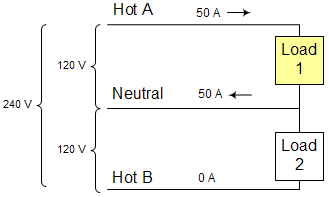
Current is flowing in on Line A, through Load 1, and out the neutral. Load 2 is off, so no current is flowing through that branch. I'm guessing you have no trouble grasping this, it's pretty straightforward.

Now consider the situation when when only L2 is loaded:


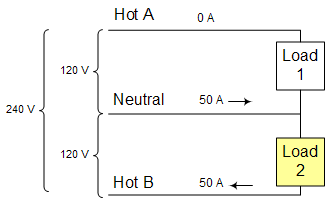
We're on the same half cycle, so the polarity of line B is the opposite of Line A, so current is flowing in on the neutral, through Load 2, and out Line B. Load 1 is off, so no current is flowing through that branch. This is really the same situation as the previous case, but because Line B has the opposite polarity, the current is actually flowing in the opposite direction than you would expect.

Finally consider the situation when when both lines are equally loaded:


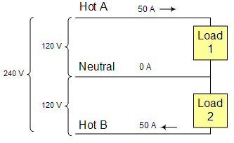
Current is flowing in on Line A, through Load 1, then the same current is flowing through Load 2, and out Line B. No current is flowing through the neutral. I'll admit, it's a difficult concept to grasp, but that's the way it works.

While the pictures are drawn with 50 amp loads, the same situation applies if the loads are 20 amps each, or even 1 amp each. As long as they are the same current draw, the same electrons flow through one load first, then the other, and not through the neutral.

Now, what happens if Load 1 and Load 2 are not the same? (I drew up these pictures a while ago for a similar discussion, but I didn't make one to cover this case, and I'm too lazy to try and re-create them now. )

Lets say Load 1 is 30 amps, and Load 2 is 20 amps. 30 amps flows in Line A and through Load 1. But then it hits Load 2 which is only drawing 20 amps: so 20 of those 30 amps flows through Load 2 and out Line B. Where does the other 10 amps go? It goes out the neutral line. As long as Line A and Line B have the opposite polarity, which they should in a proper service, the neutral does in fact carry the difference between the two hot lines. If Load 1 were 20 amps and Load 2 were 30 amps (swap the previous set of loads) then there would be 20 amps going in Line A, 30 amps going out Line B, and 10 amps going in the neutral (opposite direction from the previous set of loads.)

So, the neutral is still needed, even if it sometimes has no current. In fact, it's critical: one of the most disastrous wiring faults for an RV is an open neutral. Let's stick with the 30 amp Load 1 and 20 amp Load 2. At this point it starts to get complicated, using Ohms Law and Kirchoff's law, but I'll try to keep it simple. We can figure out the basic resistance of each load: 120 volts divided by 30 amps gives 4 Ohms for Load 1, while 120 volts divided by 20 amps gives 6 Ohms for Load 2. If the neutral wire is broken, we basically have a 240 volt series circuit of 4 + 6 = 10 Ohms. 240 volts divided by 10 ohms gives 24 amps of current actually flowing through the series circuit (remember, the neutral is broken.) This means 24 amps times 4 Ohms gives 96 volts across Load 1, and 24 amps times 6 Ohms gives 144 volts across Load 2. That's bad news! With an open neutral, you don't have the neutral connection to balance the loads, so if the loads on the two hot leads are not exactly the same, the voltage on one hot lead will rise, while the voltage on the other hot lead will drop by the same amount. Taken to extremes, with one line heavily loaded and the other line lightly loaded, one of the loads can see voltages approaching 240 volts.


Quote:
Originally Posted by LadyFitz... View Post
The result was 120v over each phase and 120v across the two legs instead 240v.
Very interesting story, I'm sure it was "exciting" while it was happening. However, I think you might have meant to say that there was 0v across the two legs instead of 240? I'm not sure how you would get 120v from each hot to neutral AND 120v between the two hots unless they figured out how to set up a 120v three phase delta with one of the neutrals being the third hot. (Or is this what they actually did???)

Thanks for the clarification/confirmation on the 120/208 wiring, I was wondering how well a coach designed for 120/240 would cope with it, I guess it varies.
__________________
Adam and Sue, and a pack of little furballs
2007 Holiday Rambler Endeavor 40PDQ Limited Edition - Cummins ISL 400
2013 Ford F-150 FX4 toad - USGear Unified Tow Brake, Roadmaster Blackhawk II Tow bar, Blue Ox baseplate
Home base near Buffalo NY, often on the road to a dog show
ShapeShifter is offline   Reply With Quote
Old 07-04-2015, 09:47 AM   #31
Senior Member
 
Winepress's Avatar
 
Join Date: Jul 2012
Posts: 1,737
Thanks, trying to get my head around this, might take a while. Thanks for your time and effort to educate.
__________________
2018 Dutch Star 4369
Everything was working fine, until it wasn't.
Winepress is offline   Reply With Quote
Old 07-04-2015, 03:01 PM   #32
Senior Member
 
wa8yxm's Avatar
 
Damon Owners Club
Workhorse Chassis Owner
Join Date: Mar 2009
Posts: 24,024
Quote:
Originally Posted by dennis45 View Post
Or, if you're really cheap, just get a 45 gal drum, paint it black and mount it on the roof with a hose to your shower. Lots of hot water for FREE!
Where I am parked.. Just now.. So long as you shower at least an hour after sunrise. UNLIMITED and TOO HOT would be words that apply.. You would need a thermostatic mixing valve to keep from getting scalded (Heck 50 feet of hose on the ground would do it.. I have around 20-feet and.. Well.... I actually showered without aid of the water heater last time.
__________________
Home is where I park it!
wa8yxm is offline   Reply With Quote
Old 04-01-2017, 11:45 PM   #33
Junior Member
 
Join Date: Jan 2016
Posts: 9
I realize this is a pretty old thread and the OP may or may not have attempted to make this conversion but I was killing some time and came across this and figured I'd post what I did a while back.

I had to change the water heater in my 5er and I admit that I sometimes have a Tim the Tool Man tendency so I figured I'd convert the new larger water heater to run on either 120V or 208/240V. My requirements were that it be automated, easy to operate, safe and meet code. This meant that when plugged into 120V power the water heater would run normally and when plugged into 208/240V power it would heat using the higher voltage. It would also need to account for mis-wired pedestals where the two 120V legs are not properly out of phase with each other.

I first replaced the wire in the water heater running from the electrical box to the heating element with 10awg wire so it would meet the requirements for the amp draw of the element when on 208/240V. I also purchased a 6000W 240V heating element (about $16) that was sized correctly for the depth of the tank. In my case, the tank is 12 gallons and it required 2" of clearance from the heating element to the far side of the tank. I have 3" with this element so plenty of room. The 6000W heating element will have about 1/4 the resistance when connected to 120V so will provide 1500W which is almost exactly the same as the 1440W that the original 120V heating element is rated for.

I printed a new wiring schematic for the side of the water heater showing the new wiring diagram so it would be clear how to wire it for any future electrician and placed a label under the outer cover marking the heating element as 240V 6000W and the part number. It can easily be rewired for 120V use if it's ever put into another camper and with or without an original heating element would function exactly as it did when shipped. I included a copy of this schematic and a parts break down on a sheet of paper and inserted it into the operators manual.

I used the existing on/off switch inside the heater and associated thermostat as the on/off switch for a 120V 40A three pole relay (about 16$). When the thermostat and on/off switch are both closed, the relay is activated and all three poles close passing L1, L2 and N through the relay to a second 40A 240V 3PDT relay (also about 16$). If this relay receives a 208/240V input on the coil it closes and passes the 208/240V directly to the heating element. Since L1 and L2 will have exactly the same load, there is no N to the element as the loads are balanced and it is not required, nor is there a place to connect a N wire on any 240V heating element. If there is only 120V present from the 1st relay, the coil on the second relay remains open and the non-energized output on the 3PDT relay passes neutral and 120V directly to the heating element with one hot wire and one neutral wire.

I placed the two relays on a din rail in a small electrical box and mounted it in the compartment next to the water heater. In my camper I use a load shed device that will give priority to the microwave if it's running and will switch off power to the water heater so I had to keep the existing 120V breaker in place for the switched on off circuit and I installed an additional 30A double pole breaker in the power panel and ran a 10awg Romex wire to the water heating compartment to the new relay box. This new wire provides the power for the heating element at 120/208/240V and the existing 120V 12awg Romex from the load sharing circuit powers the on off relay for the new wire. The new breaker is oversized for the 120V 12.5A draw but not for the 10awg wire and any short will still trip the double pole 30A breaker. At 25A it will draw almost exactly the 80% recommended continuous load the 30A breaker is designed for. The 10awg wire is adequate for 30A so is properly sized for the design.

Now if I'm connected to any source of 120V only power, ie: generator, 30A, 20A, etc, the water heater works at the same 1500W as original and will use about 12.5A. When I plug into a 50A pedestal the water heater switches to 240V and heats at 6000W using 25A.

I used an online calculator to determine the Btu equivalent of the 1500W and 6000W heating element and learned that a 6000 watt 240V element produces 20,460 Btu at 240V and 5115 Btu at 120V. The stock 1440 watt 120V produced 4910 Btu. The gas heater runs at 12,000 Btu and can still be run in parallel with the electric element at any available voltage. I have not experienced any short cycling issues, however the element does cycle on for a shorter duration than in the original design. If I had experienced short cycling issues I would have added a few more dollars (oddly, about $16) to the build and included a heat sequencer relay to delay the on cycle each time the element was switched off.

So the cost of the conversion ended up being a little funny in that the two relays were about $16 each, the heating element was $16 and the box they were mounted in was also $16. I already had a piece of din rail and the wire so my cost out of pocket was $64 and the time I spent designing and making the change was purely for the entertainment value and for me was well worth the $64 cost.

Is this necessary, no, absolutely not. The existing system works as designed and does it well and for most if not everyone is better left alone. I simply have a faster recovery time now when connected to 208/240V power and it's mostly just a Tim the Tool Man type upgrade that my wife often shakes her head at, but I find it fun and sometimes challenging to do these kinds of things and it helps keep my mind sharp.

If anyone does attempt a similar conversion, my only advice is to do it properly. That may require help from an electrician and some time to become educated in how all the parts work. Do not use undersized wiring and components. Also, proper schematics and labeling is a must. You don't want to have a Frankenstein like mystery system that any future owner/user/service tech will not be able to safely and easily operate and repair.

I keep myself pretty busy so if anyone has questions I will try and answer them when I can, but please don't expect an immediate reply.
ipgenie is offline   Reply With Quote
Old 04-02-2017, 07:30 PM   #34
Senior Member
 
dirko's Avatar
 
Ford Super Duty Owner
Join Date: Dec 2002
Location: Alpine, UT
Posts: 549
When we want a lot of hot water, for example when there are multiple people taking a shower one after another we simply turn on the electrical and the propane at the same time.

It is hard to use water faster than it can be heated unless you really try hard. No cost, no hassle.
dirko is offline   Reply With Quote
Old 04-02-2017, 11:12 PM   #35
Junior Member
 
Join Date: Jan 2016
Posts: 9
Yup, the water heater works great as designed just like most of the systems in any given RV.
One of the cool things about having an RV is the opportunity to make it your own and customize it how you want. I'm sure most of us have made changes or had changes made by others to improve or customize our RVs, and for any change one owner finds useful or worth their time there is another owner who feels like it's not worth the cost or effort.
This is simply an example of one of many that I made to my RV posted here in reply to a question someone else posted. Hopefully it's helpful to others.
ipgenie is offline   Reply With Quote
Reply

Tags
heater, water heater, water, heat


Currently Active Users Viewing This Thread: 1 (0 members and 1 guests)
 

Posting Rules
You may not post new threads
You may not post replies
You may not post attachments
You may not edit your posts

BB code is On
Smilies are On
[IMG] code is On
HTML code is Off
Trackbacks are Off
Pingbacks are Off
Refbacks are Off


Similar Threads
Thread Thread Starter Forum Replies Last Post
newbie water heater ? kitakat11 Class A Motorhome Discussions 3 05-27-2015 09:58 PM
Suburban water heater; electric light stays on driedl Newmar Owner's Forum 10 10-19-2014 07:34 PM
Water Heater Intermittently Does Not Start georgegdc RV Systems & Appliances 10 10-03-2014 05:37 PM
Water Heater Woes Gadget Man RV Systems & Appliances 11 05-01-2014 09:53 PM
Atwood Water Heater Problems denochs RV Systems & Appliances 5 04-02-2014 05:50 AM

» Featured Campgrounds

Reviews provided by


All times are GMT -6. The time now is 07:27 AM.


Powered by vBulletin® Version 3.8.8 Beta 1
Copyright ©2000 - 2024, vBulletin Solutions, Inc.