 |
 04-20-2016, 10:03 AM
|
#1
|
|
Senior Member
Newmar Owners Club Freightliner Owners Club Spartan Chassis
Join Date: Apr 2012
Location: ON THE ROAD...SOMEWHERE
Posts: 6,973
|
Looking to Re-Cable Battery Bay - Suggestions?
Long story short, a technician that installed my BMK kinda screwed it up and I need to move the shunt to a new location. At the same time I'm finding my battery cables are arranged in a way that makes it difficult to push back in and the cables are very stiff. I'm going to need to move some cables to the side of the bay for the shunt.
Anyway...I'm looking at replacing some of the cables to get them the correct length for some repositioning. I really don't quite know what cables are there but I've heard welding cables are the way to go because they are more flexible than other battery cable types.
Any thoughts?
__________________
Don, Sandee & GSD Zeus. Guardian GSDs Gunny (7/11/15) & Thor (5/5/15)
2006 2015 DSDP 4320 4369, FL Chassis, 2013 CR-V 2020 Jeep Overland, Blue Ox Avail, SMI AF1.
[SIGPIC][/SIGPIC]
|

|

|
 |
Join the #1 RV Forum Today - It's Totally Free!
iRV2.com RV Community - Are you about to start a new improvement on your RV or need some help with some maintenance? Do you need advice on what products to buy? Or maybe you can give others some advice? No matter where you fit in you'll find that iRV2 is a great community to join. Best of all it's totally FREE!
You are currently viewing our boards as a guest so you have limited access to our community. Please take the time to register and you will gain a lot of great new features including; the ability to participate in discussions, network with other RV owners, see fewer ads, upload photographs, create an RV blog, send private messages and so much, much more!
|
|
04-20-2016, 10:25 AM
|
#2
|
|
Senior Member


Join Date: Apr 2011
Location: Powell River, B.C.
Posts: 31,500
|
There are different quality of cables out there , and after reading your post and thinking about the issue I have with my chassis battery cables and the roll out battery tray; the stiff cables twist the post clamps around no matter how tight I have them. I will also consider a change .
The only problem I can see is this ; I've spent a fair amount of time around welding equipment and done arc welding for 40+ years and I've never seen welding cables of the gauge that my chassis battery cables are, so how best to determine if the welding cables will carry the amps required to feed all the battery power to the starter, biggest arc welder I ever used was 300 amp , if memory serves; so I don't know if that same cable would carry the power from a pair of 950 CCA 12 volt to feed the starter. 
__________________
99DSDP 3884, Freightliner, XC, CAT 3126B, 300 HP /ALLISON 3060
2000 Caravan toad, Remco & Blue Ox.
|
|
|
|
|
04-20-2016, 10:32 AM
|
#3
|
|
Senior Member
Join Date: Jan 2015
Location: Oroville, CA
Posts: 3,133
|
__________________
Bill, Kathi and Zorro; '05 Beaver Patriot Thunder
2012 Sunnybrook Harmony 21FBS (SQEZINN)
2007 Jeep Grand Cherokee Overland
|
|
|
|
|
04-20-2016, 10:49 AM
|
#4
|
|
Senior Member
Newmar Owners Club Freightliner Owners Club Spartan Chassis
Join Date: Apr 2012
Location: ON THE ROAD...SOMEWHERE
Posts: 6,973
|
Quote:
Originally Posted by Skip426

...I've spent a fair amount of time around welding equipment and done arc welding for 40+ years and I've never seen welding cables of the gauge that my chassis battery cables are, so how best to determine if the welding cables will carry the amps required to feed all the battery power to the starter, biggest arc welder I ever used was 300 amp , if memory serves; so I don't know if that same cable would carry the power from a pair of 950 CCA 12 volt to feed the starter. |
HMMMM...that is sobering. LOL According to one table they say 4/0 is good for 600 amps up to 50'. A pair of 950 CCAs to the starter...  Hadn't even considered that aspect. 
Perhaps I could just use welding cable for the house battery system?
Maybe I should just leave it alone unless we find something specifically wrong?
__________________
Don, Sandee & GSD Zeus. Guardian GSDs Gunny (7/11/15) & Thor (5/5/15)
2006 2015 DSDP 4320 4369, FL Chassis, 2013 CR-V 2020 Jeep Overland, Blue Ox Avail, SMI AF1.
[SIGPIC][/SIGPIC]
|
|
|
|
|
04-20-2016, 11:48 AM
|
#5
|
|
Senior Member
Join Date: Apr 2012
Location: CLEARWATER, FLORIDA
Posts: 1,052
|
Those huge cables are needed to minimize loss when boondocking, and every milli-amphour counts. For starting, you will have some voltage drop, but it will not keep you from starting just fine. More normal sizes are all that are needed, and all that the new coaches come with.
Tom
__________________
Tom & Jan ---- Westwing43 (RVM28)
2008 NEWMAR MOUNTAIN AIRE 4528
Pulling a 2014 CHEVY CAPTIVA
|
|
|
|
|
04-20-2016, 05:35 PM
|
#6
|
|
Senior Member
Join Date: Feb 2010
Posts: 4,654
|
Larger size is to reduce voltage drop at high currents.
Welding wire is a generic term for a type of cable often specified for sound stage work.
Cannot remember true name but it has finer strands to allow more copper square surface area.
Visit a well stocked MOM AND POP or private operator battery store or same welding supply and they can make custom cables usually for cost of materials and little if any labor.
You can use longer cables with a "service loop" that allows the cables to move as the tray is rolled out.
Please post some photos so we can see what you have.
__________________
Tony & Lori
1989 Country Coach Savannah SE
|
|
|
|
|
04-20-2016, 08:11 PM
|
#7
|
|
Community Moderator
Join Date: Sep 2011
Location: Between the Oceans
Posts: 8,034
|
generally, 2/0 gauge welder cable is adequate for all battery connections and from/to inverter. my cc is that. however, mangum inverter recommends using 4/0 cable between battery pack and inverter for its 2800w or up inverters. in your case 2/0 is probably what you need.
__________________
Steven & Polly
2000 Country Coach Intrigue 40' ISC 350
2018 Ford Explorer 4WD
|
|
|
|
|
04-20-2016, 08:19 PM
|
#8
|
|
Senior Member
Country Coach Owners Club Solo Rvers Club iRV2 No Limits Club
Join Date: May 2011
Location: Vancouver, WA
Posts: 37,725
|
We have 4 925 CCA batteries. Have not checked to see what the cable size is though.
__________________
2009 45' Magna 630 w/Cummins ISX 650 HP/1950 Lbs Ft, HWH Active Air
Charter Good Sam Lifetime Member, FMCA,
RV'ing since 1957, NRA Benefactor Life, towing '21 Jeep JLU Rubicon Ecodiesel
|
|
|
|
|
04-20-2016, 08:46 PM
|
#9
|
|
Senior Member
Newmar Owners Club Freightliner Owners Club Spartan Chassis
Join Date: Apr 2012
Location: ON THE ROAD...SOMEWHERE
Posts: 6,973
|
The good news is that the problems I was having with the inverter seem to be corrected. It appears I had a bad connection and the inverter was not getting a proper 12V from the house batteries. This could have originated any where from the battery terminals to the battery cut off switch to the inverter. Since Newmar was testing the BIRD I think there is a possibility they pulled the battery tray out in the process and maybe that exposed a connection problem in that area. When I pulled the tray last night I may have "fixed" it. The other possibility is that after exercising the battery cut off switch several times I may have "fixed" that too.
I really wouldn't be getting all down in the weeds on this project if it wasn't for the BMK and moving the shunt to a location for it to do its job. It is important that I get it set up correctly.
I've been thinking about this all day. Here is what I think I am grasping. Some of this is pretty basic but I like to cover these to make sure I'm getting it right.
1. Welding cable is finer copper strands compared to standard batter cable. This helps in flexibility. This could be an advantage to create a "service loop" as suggested by TQ60. This would be especially important for getting cable to a better location for the BMK shunt.
2. There is some concern about the covering on welding cables because it is not SAE approved and will more readily reacts to gas/diesel. Since I am only looking to rewire the house batteries to the inverter they won't be in an environment that should subject them to chemicals like this so I don't think I should worry about that.
3. Welding cable has a thinner covering so one has to be more careful about routing around sharp edges. The other concern about the cover is that I would have is how some cable is directly behind the batteries so I need to evaluate the routing and perhaps avoid this all together.
4. I have read that putting lugs on welding cable is more difficult both in connecting them and getting the proper lug/terminal size. I also learned the lugs need to be crimped and soldering for best thermal protection. I expect that my installer has the experience in this area. If not...gonna have to think this out more.
5. Typical MINIMUM temp ratings for welding cable equals or exceeds 90*C while battery cable is 85*C. Most quality cables of either kind are closer to 100-105*C No big difference there. Still, given the relatively high ambient temps of my battery bay, I will want one that is on the higher end of the temp rating scale.
Now some math...assuming I have this figured out correctly.
The absolute max charging I have ever seen is 75 amps so that number is pretty simple to figure out.
The other part is how many amps will I pull if inverting the max? that max my inverter will provide is 2800W at 120V or 30A. If I was running full bore that means I need to pull 2800W of power out of the batter at 12V which translates to 233A. So, if I use cables capable of passing 500A up to 50' the information I have says 3/0 does the job. If I want to further reduce voltage drop I don't see a reason to skimp and why not just go 4/0.
Of course, once we get the tray out and evaluate what I currently have I bet it turns out to be 4/0 so common sense trumps math. LOL.
If I don't get a good, fuzzy feeling from this installer, I will hold off until I get back home and re-evaluate. So far, he seems to be a pretty fair and straight shooter.
__________________
Don, Sandee & GSD Zeus. Guardian GSDs Gunny (7/11/15) & Thor (5/5/15)
2006 2015 DSDP 4320 4369, FL Chassis, 2013 CR-V 2020 Jeep Overland, Blue Ox Avail, SMI AF1.
[SIGPIC][/SIGPIC]
|
|
|
|
|
04-20-2016, 08:47 PM
|
#10
|
|
Senior Member
Newmar Owners Club Freightliner Owners Club Spartan Chassis
Join Date: Apr 2012
Location: ON THE ROAD...SOMEWHERE
Posts: 6,973
|
Quote:
Originally Posted by CountryFit
generally, 2/0 gauge welder cable is adequate for all battery connections and from/to inverter. my cc is that. however, mangum inverter recommends using 4/0 cable between battery pack and inverter for its 2800w or up inverters. in your case 2/0 is probably what you need.
|
Yep...I have 2800W and found that info in the owner's manual. THANKS for pointing that out!!!
__________________
Don, Sandee & GSD Zeus. Guardian GSDs Gunny (7/11/15) & Thor (5/5/15)
2006 2015 DSDP 4320 4369, FL Chassis, 2013 CR-V 2020 Jeep Overland, Blue Ox Avail, SMI AF1.
[SIGPIC][/SIGPIC]
|
|
|
|
|
04-21-2016, 07:48 AM
|
#11
|
|
Senior Member
Join Date: Feb 2010
Posts: 4,654
|
Look up Thomas Betts connectors or Google crimp connectors and you will see more than you expect.
Good to do as to properly do this you should use correct connectors.
Many stock most and will under size meaning use connectors for larger wires and crimp down to smaller wires.
They are color coded for wire size and rings indicate crimp points.
No need to solder but with a good torch for rapid heating and correct solder it can be done if one wants to but not needed if proper connector and tool used.
They do have heat shrink tubing that has heat activated glue sealer inside that can be used to seal them up to protect from vapor attacks but not commonly stocked but can be ordered.
Good quality scotch 33 or 88 can be stretch wrapped over the connections and do just fine.
Use red for hot and blue or black for ground.
For service loops imagine holding a jump rope.
Lift one arm and the rope shifts but does not stress
Same for your battery.
Have a length that is either along side or over top of battery tray that will allow tray to move fully without adding any stress to either end.
A couple extra feet will not cost much in money or voltage loss so take your time here to get it right.
Using water hose to perform "proof of concept" works well here.
Attach with a zip tie or tape and test the fit and operation.
Reroute and test until it works well.
Leave extra to allow for replacement of ends down the road if needed and for servicing the batteries.
Mark with colored tape so you know the lengths and take your hose with you to the cable place and tell them what the marks mean.
Know your wire size and color code and style for your connectors and review your project and materials before any wires are cut or crimped.
__________________
Tony & Lori
1989 Country Coach Savannah SE
|
|
|
|
|
04-21-2016, 04:37 PM
|
#12
|
|
Senior Member
Newmar Owners Club Freightliner Owners Club Spartan Chassis
Join Date: Apr 2012
Location: ON THE ROAD...SOMEWHERE
Posts: 6,973
|
The job is done!
Thanks for suffering my OCD tendencies to work things through. It was a good thing I got this done.
It was a cool, rainy start at Solar Energy Systems at Nappanee, IN. Brian and his team tore into the project at about 6:15 AM we found several problems caused by a previous "certified" Magnum Energy service tech.
1. 2 lugs he made were loose enough to cause some arcing.
2. The BMK shunt was installed in the wrong place.
3. A couple smaller gauge butt connectors were poorly done.
4. Found a couple other loose cable connections with one showing some arcing.
5. Found that there was a minor inefficiency in house batter cable connections.
6. Load tested 4, 1.5 year old house and 2 original chassis batteries.
The remedies were:
1. Examine each and every lug, correct any deficiencies, replace black tape with heat shrink.
2. Replaced all 3/0 battery cables with 4/0. This was specific to the short cables tying the 6V batteries together to create 12V. One was corroded and the three others were original. I decided that 4/0 was worth the upgrade to match the 4/0 welding cable from the batteries to the inverter.
3. Installed BMK shunt and control module in the battery bay. Then we connected all negative returns (not just the inverter) to the shunt.
4. Load testing on the house batteries was a mixed bag. At 56* they ranged from 710 to 1000 CCA on the load test meter. At 56* we should have expected to see all in the 1000 CCA range. I will talk with Lifeline after I do an equalization charge tonight. This might be a result of the + and - cables being connected to the same 6V pair. More correctly the proper wire plan is to connect to the + on the lead in to all batteries and the - on the last negative.
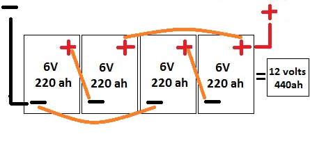
In the above picture, my + was tied to the second from the left + lug instead of the one on the farthest right. The 2 right side batteries were the lowest CCA readings.
Another possible factor could have been that one of the short connectors was corroded and perhaps also causing some imbalance during charging.
5. Load tested the starter batteries while at it. They read 800 CCA instead of the rated 975 CCA. I decided it was time to replace them since these were the originals and I plan on keeping the coach for a few more years and now is as good as anytime. BTW...they were only showing 12.4V when ever shore power was off.
I am running up to Spartan factory this weekend with a Monday appointment for my annual service. When that is done we will come back down to Solar Energy Systems for phase 2 of battery bay work.
The problem is that in the summer I have seen battery temperature sensor reading as high at 130* that held steady well into the cooler evening. My battery bay is directly above the exhaust.
We will:
1. Install heat reflecting insulation on the outside walls of the battery bay.
2. Create 2 vents to draw in fresh air. One will be into the front of the battery bay from below and the second one will be on the back edge of the battery bay wall near the top. This, by itself, will create some air flow.
3. Add a fan to either/both vents with a thermistor/thermostat to activate fan(s). That will be directly connected to the chassis battery so that even if the engine is off power is available to keep the fans running until the desired temp is reached. I expect I will look to get temps down to 100*F.
4. Run another load test to see if the equalization along with upgraded cables changes anything.
__________________
Don, Sandee & GSD Zeus. Guardian GSDs Gunny (7/11/15) & Thor (5/5/15)
2006 2015 DSDP 4320 4369, FL Chassis, 2013 CR-V 2020 Jeep Overland, Blue Ox Avail, SMI AF1.
[SIGPIC][/SIGPIC]
|
|
|
|
|
04-21-2016, 07:10 PM
|
#13
|
|
Senior Member
Join Date: Feb 2010
Posts: 4,654
|
Use Google for high volume low amp fans.
Was able to find some surplus pulls that retailed for about 80 bucks a pop for 5 each.
Ball bearing with 120 to 200 ish CFM at 0.5 amps at 12 volts.
Get something like those and have them run anytime shore cord plugged in or charger operating.
__________________
Tony & Lori
1989 Country Coach Savannah SE
|
|
|
|
|
04-25-2016, 09:36 PM
|
#14
|
|
Senior Member
Join Date: Feb 2012
Location: Small Town USA , California
Posts: 1,349
|
I made all of my Battery/Inverter cables myself from old used Welding Cable about 10 years ago or so. Even though the outside shielding was worn a little , the copper inside was bright and shiny like new. I borrowed a heavy duty crimper and used the heavy duty shrink tube with the adhesive. They are still in great shape and working fine.
|
|
|
|
|
|
Currently Active Users Viewing This Thread: 1 (0 members and 1 guests)
|
|
|
 Posting Rules
|
You may not post new threads
You may not post replies
You may not post attachments
You may not edit your posts
HTML code is Off
|
|
|
|
 » Recent Discussions
 |
|
|
|
|
|
|
|
|
|
|
|
|
|
|
|
|
|
|
|
|
|
|
|
|
|


 Linear Mode

